New topic to move previous discussion on tip speed ratio to.
An easy to understand paper on the subject:
http://mragheb.com/NPRE%20475%20Wind%20Power%20Systems/Optimal%20Rotor%20Tip%20Speed%20Ratio.pdf
New topic to move previous discussion on tip speed ratio to.
An easy to understand paper on the subject:
http://mragheb.com/NPRE%20475%20Wind%20Power%20Systems/Optimal%20Rotor%20Tip%20Speed%20Ratio.pdf
Maybe I worded it wrong. At the moment I lack even the knowledge to use simulation tools. A basis is good, like knowing what a drag polar is.
https://www.fieldlines.com/index.php/topic,149676.0.html
My design necessitates a very low tip speed ratio. I’d like to learn where I can find airfoils for that and how to evaluate them.
I believe airfoiltools have some profiles for windmills. The selection and design og airfoils for a windmill, if it is to be more than a hobbyist project, I believe is an advanced task that requires very specific qualifications. I could not help you with this except saying that a low tip speed ratio is a good thing because that means you want a low efficiency wing. The next question you might ask yourself is how to best put that waste of efficiency into positive use in your design.
I believe there are some formulas to say somethibg about the L/D of a wing based on the 2D profile curves and the aspect ratio of the wing. You might also find something for windmills. You could use this as a starting point to see what performance you could expect from a design. But these days there are no reasons not to do a computer based simulation before building the real thing
The proof-of-concept won’t be more than a hobbyist project. I first would need to determine if the thing works at all, only then should I worry about efficiency I think. My thinking is to just choose an airfoil that looks good and call it a day, for now.
I’ve seen it repeated that a low-tip-speed ratio equals low efficiency. I really need to understand that thoroughly to optimize the design, or change it.
http://mragheb.com/NPRE%20475%20Wind%20Power%20Systems/Optimal%20Rotor%20Tip%20Speed%20Ratio.pdf
I keep wondering if just increasing the number of blades won’t solve the problem.
(Please remember this free advice is totally unqualified)
The wing tip ratio is more or less the windmill version of a wing’s lift-to-drag ratio. Except now the wing rotates instead of flies forward.
If you build the windmill with low efficiency, you could add more blades, and they would not be interfered by the wake of the forward blade. The efficiency I would think is unchanged. You just get a larger wing area. You might have longer blades for the same effect, if that made your build easier.
I am still puzzled why you would design a windmill (?) starting with a requirement of low efficiency. Normally limiting efficiency would be a result of another design choice (eg. the wings are single skin kites and I cant build them with greater L/D ratio than 3).
To use the lower tip speed ratio to good use would be eg: minimizing the radius of your windmill, thicker wings with space for stiffening, bridles, etc, that would make completing your design easier
Noted. This just came up, I had expected the other topic to stay more theoretical.
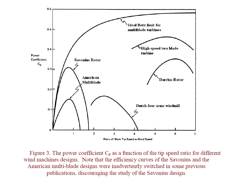
The paper gives some graphs and tables:
The table and the graph agree I think I shouldn’t try to lower de TSR to much lower than 2. At a TSR of 2, the efficiency looks to be still around 93 percent of the efficiency of a turbine with a TSR of 6.5 (0.515/0.556).
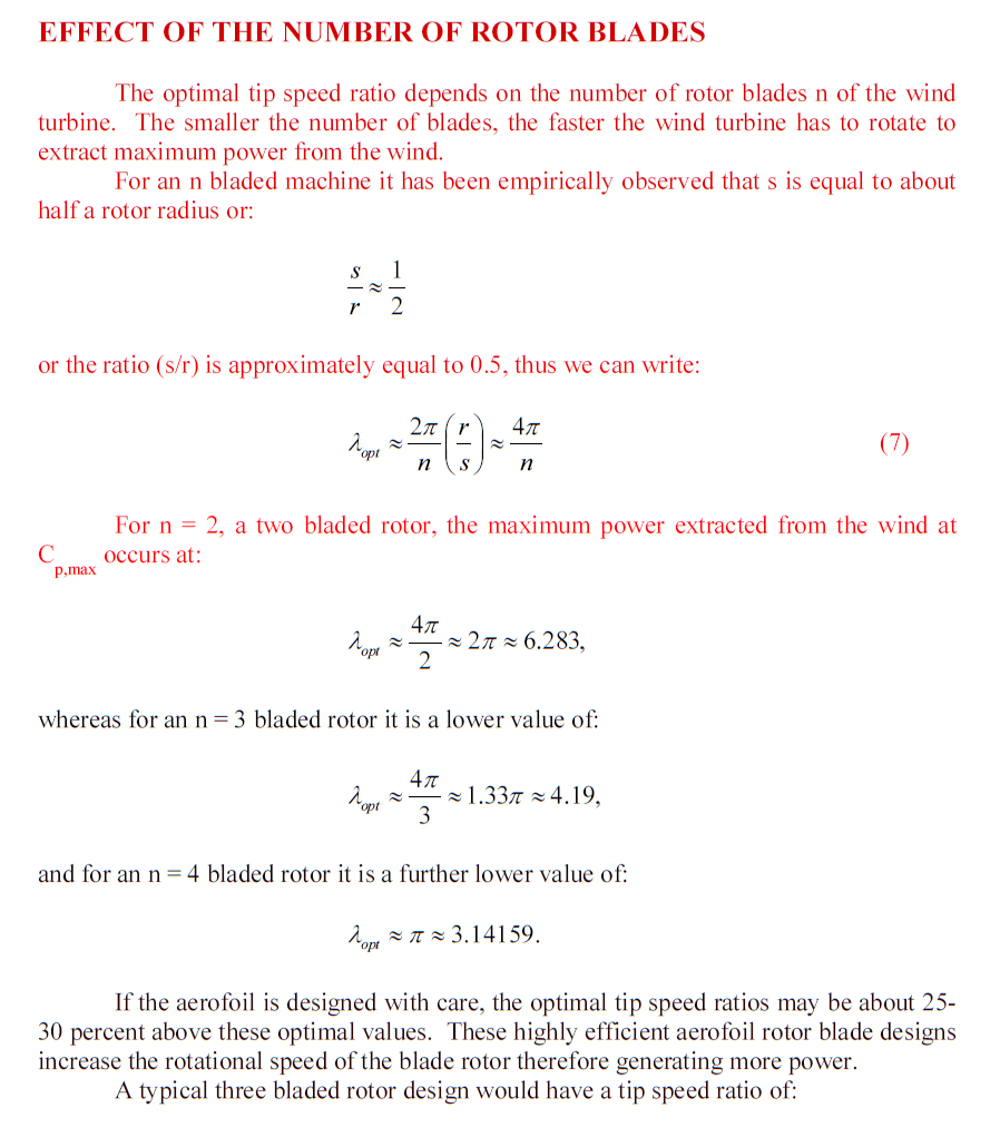
I don’t know how applicable the “empirical observation” that s/r is 1/2, to my design, as my design, like those of @Rodread and @someAWE_cb doesn’t have a hub. Ignoring that, it becomes easy to calculate optimal TSRs:
For 5 bladed rotors: 4pi/5 = 2.5; for 6 bladed rotors, 4pi/6 = 2.1; for 7 bladed rotors, 4pi/7 = 1.8, for 8 bladed rotors, 4pi/8 = 1.57.
To me it looks like I should aim for 6 or 7 blades. 4 blades would have the tips moving at 30 m/s (108 km/h) in 10 m/s wind, that’s too fast.
What would be some things to look out for when designing a 6 or 7 bladed rotor? Maybe it becomes easy for the TSR to get too low? Maybe the band of windspeeds that it would work efficiently in is very small? I’d like to optimize the thing to work well in 8-12 m/s wind.
I thought the Betz limit did not care about the design of the harvesting device. In the graph above it seems there is a dependency on tip speed ratio vs betz’ limit…
I think that graph was copied from a 1980 book.
I looked a bit further, here is the original unabridged paper the article I linked was based on, with more references. I haven’t read that yet.
http://mragheb.com/Wind_turbines_theory_the_betz_equation_and_optimal_rotor_tip_speed_ratio.pdf
That same graph has been endlessly referred to, over and over and over and over, for decades. often with the comment that the American farm water-pumping windmill curve, and the Savonius curve, were each mislabeled as the other. One thing that hit me decades ago was how the entire world would just keep repeating the same old graph over and over, with nobody ever changing it or coming up with a new version. I guess it persists to this day. OK if the “Professor Crackpot” Savonius can reach a Cp of .3, please tell me how. Let’s think about it logically: half of the Savonius swept area is traveling upwind, using power. The half that produces power is traveling downwind, reducing the relative wind speed, so it is not efficient. The only way you could get a Cp of .3 for the whole machine would be if the power-producing half of the machine was operating at the Betz limit of ~.6, and if the power-losing, upwind-traveling half had no losses. In other words, the idea of a Cp of .3 for a Savonius implies some miraculous “perfect performance” which is impossible since the downwind-traveling half cannot physically operate at high efficiency due that downwind travel, and the upwind-traveling half cannot possibly offer zero drag due to the enhanced windspeed it must push upwind into. On the other hand, the American farm water-pumping windmill, which was never intended to have high efficiency, so much as high reliability, and low intermittency, is still reasonably efficient, with the entire rotor fully exposed to the wind in a productive orientation, so a Cp of .3 is more believable for the American farm windmill. Therefore, I do not believe the two figures were reversed and are now correct, but instead it looks like they are reversed to this day. The silly thing is, after decades of repeating this graph, to this day people do not even know what they are looking at, no matter how many equations they can cite and repeat… Wind turbine design need not involve a lot of math or analysis. It is like riding a bike or crossing the street. Most of the factors beginners overanalyze then fail to grasp can be ignored. All the intricate analysis of airfoils etc. can similarly be ignored. Most any reasonable airfoil works fine. You just have to get the proportions right, within reason. Look at what works, copy it. The amount of info you need will fit on an index card - no need for all the complex analysis and endless equations. Wind energy is simple - either you know how to do it or you do not. Attempting to pick apart the theory in minute detail, then coming to wrong conclusions, due to still not really understanding it, is where this stuff leads. Endless formulae won;t help you if you don’t have a feel for it, informed by what is known to work. I can build great turbines in my sleep, seldom using any analytical tools beyond a measuring tape, a protractor, some calipers, and my eye. Make an airfoil that looks like an airfoil and it will work fine. Your chord and setting angles, number of blades, twist profile, etc. etc., etc., are just as influential as your choice of airfoil. No need to try to optimize the airfoil in most cases. There are so many other factors that affect performance than the choice of airfoil. And all these factors are interrelated - changing one affects all the others. In many cases, too “good” of an airfoil will work against performance due to all the other factors. Windmills are like any other aircraft - if it looks right, it flies right.
How and why?
Windy:
I knew that one would pique someone’s curiosity.
Before I answer your question, see if you can figure out a possible answer yourself, OK?
I’m not designing optimized wind turbines so I wouldn’t feel comfortable answering questions about that. One answer I expect you may give, like you always do, is overspeed protection. You’d need the extra drag for that. I’m not sure I agree. Lower drag airfoils may help in starting the wind turbine in lower winds, raising the capacity factor, along with higher solidity and lower specific power.
Your message advocates going about things in series, first build your prototype, then worry about the rest. I like doing things in parallel. Build a janky prototype but also at the same time begin your journey of understanding the next steps.
Well you did mention higher solidity rotors - there’s an example right there. If you have a high solidity rotor, and you use high performance airfoils, at a high angle angle of attack (flat setting angle), you will have put too much blade into the rotor and your performance would be better using less aggressive airfoils. High-lift airfoils also have high drag. Lower-lift airfoils slice through the air more easily.
Just as an internal combustion engine has an optimal (stoichiometric) fuel-air mixture, a wind turbine has an optimal blade-air mixture. In both cases, you want way more air than either fuel or blade, for highest performance.
If a beginner automotive wannabe thinks the only thing that matters is getting as much fuel as possible into the cylinders, a too rich mixture will ruin the performance. Same with a wind turbine: Too many blades, too wide of a chord, too high-lift of an airfoil, too high of an angle of attack, all amount to the same problem: too rich of an air-blade mix. If you have a high-solidity rotor, use a weaker airfoil.
Beyond that I do not think a high-drag airfoil hurts startup - actually it would help as long as the high drag is caused by a high-lift profile, which helps startup. The most important thing for startup is high-solidity and a steeper pitch, which (optimally) translates to a lower angle of attack, which is helpful for less drag and therefore better performance at higher speeds.
Another example of using less-aggressive airfoils is indeed related to overspeed protection. “Stall-control” turbines of “The Danish Concept” intentionally choose low-lift (crappy?) airfoils that have very little camber, and which stall easily. The overspeed protection is by limiting RPM through the grid frequency. The crappy airfoils then stall and keep the rotor from a runaway situation. Well, unless the wind gets ridiculously strong in which case they have centrifugally-deployed tip brakes that need to be manually reset after the storm passes…
Anyway, what I’ve been warning about is what I see as a fixation on the finer details appropriate for fine-tuning an already useful and good-performing device. If you don’t know enough of the basics to get something working reasonably well, it is a bad use of mental energy trying to fixate on the details of fine-tuning, and how many formulae you can fit on page after page of mathematical analysis, resulting in paralysis. Sitting around trying to see how much complex math you can fit into page after page of stuff that wind people already know without even doing the math, is a waste of time if you don’t have a basic system that is working well. It doesn’t take much math to get there, just a willingness to stop overthinking and start doing.
![]()
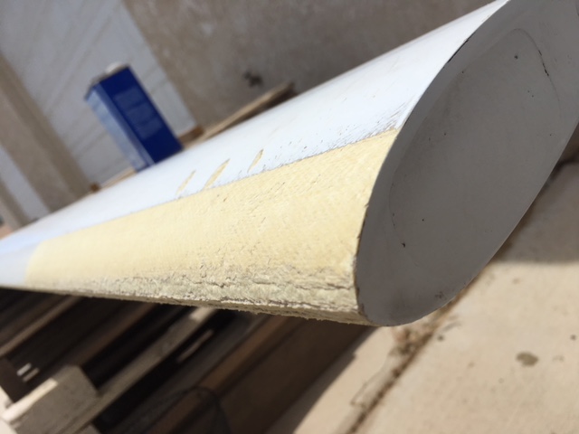
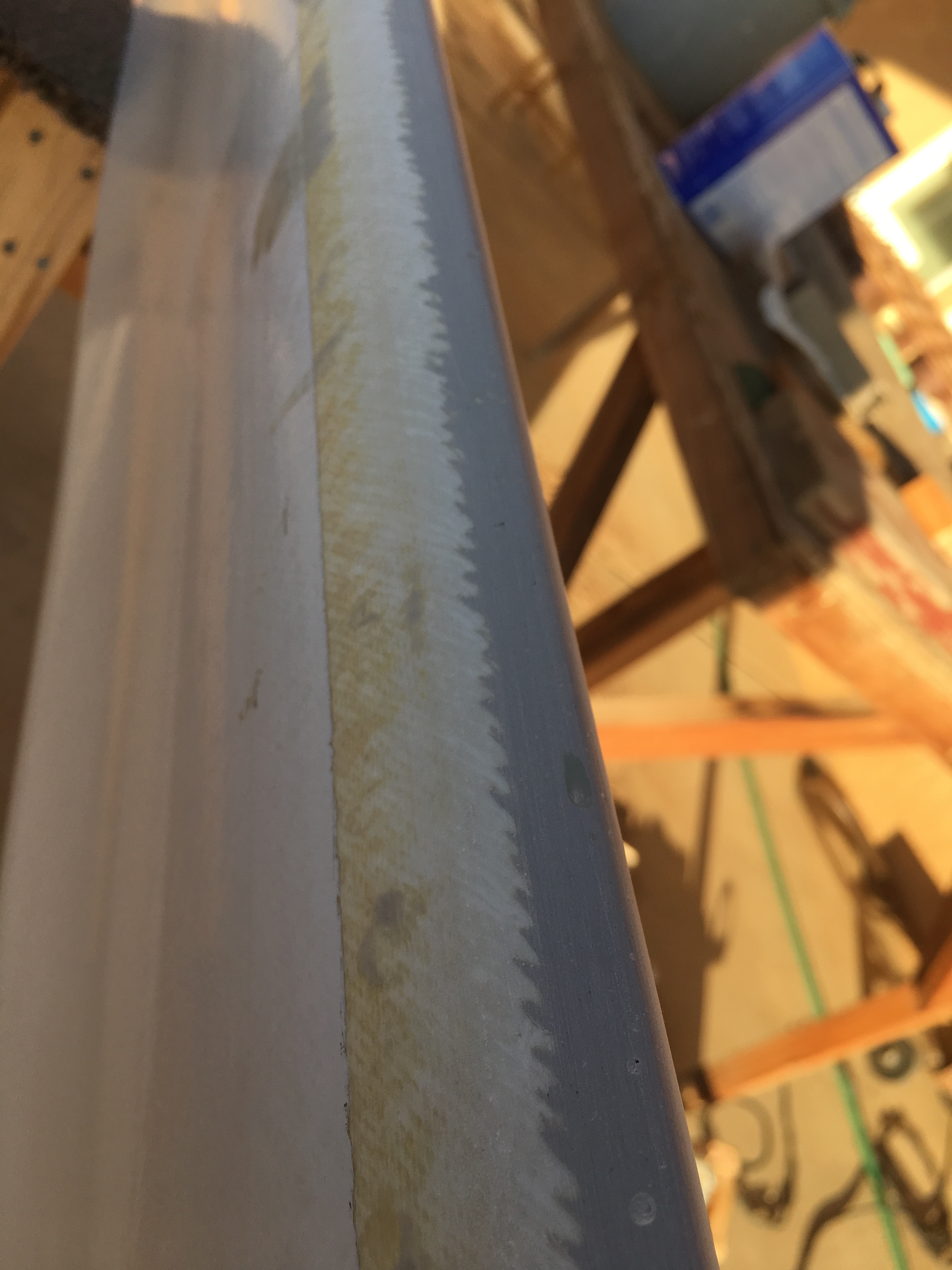
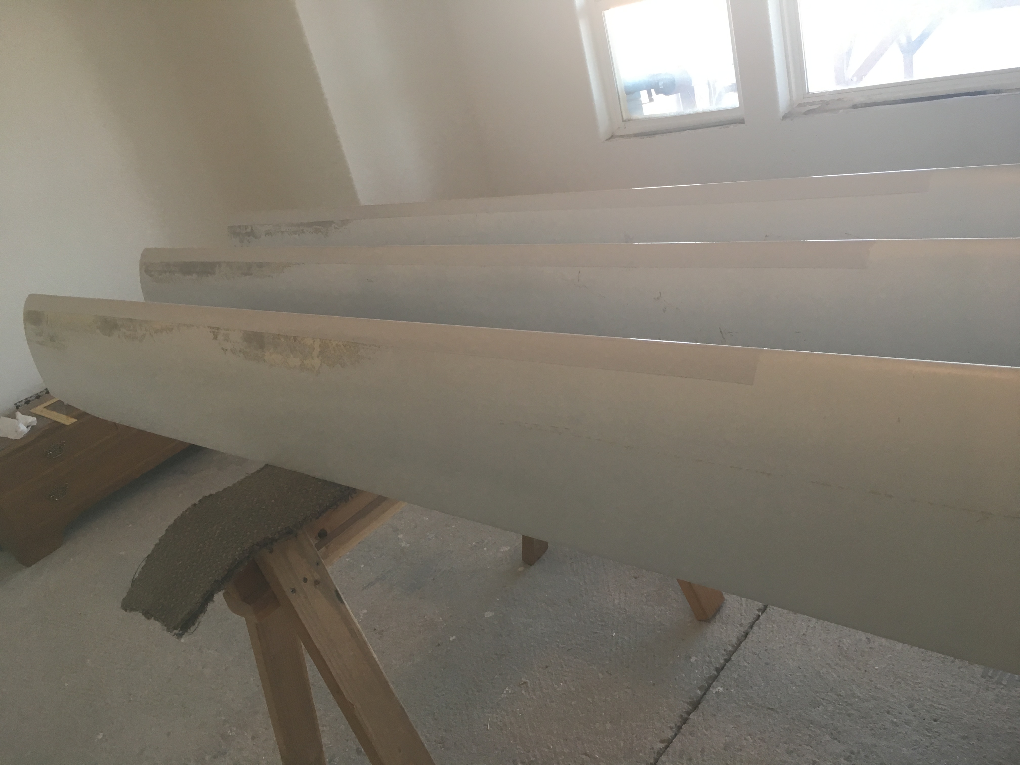
OK here’s a funny one: I was asking my friend who services utility-scale turbines in Hawaii for advice repairing the leading edge erosion on the blades of one of my 10 kW turbines. In our conversation he mentioned this:
So there you have it, right there. “Improving” the airfoils on a stall-regulated turbine ruined the machine. Overspeed protection: It’s not the main thing, it’s the only thing! 
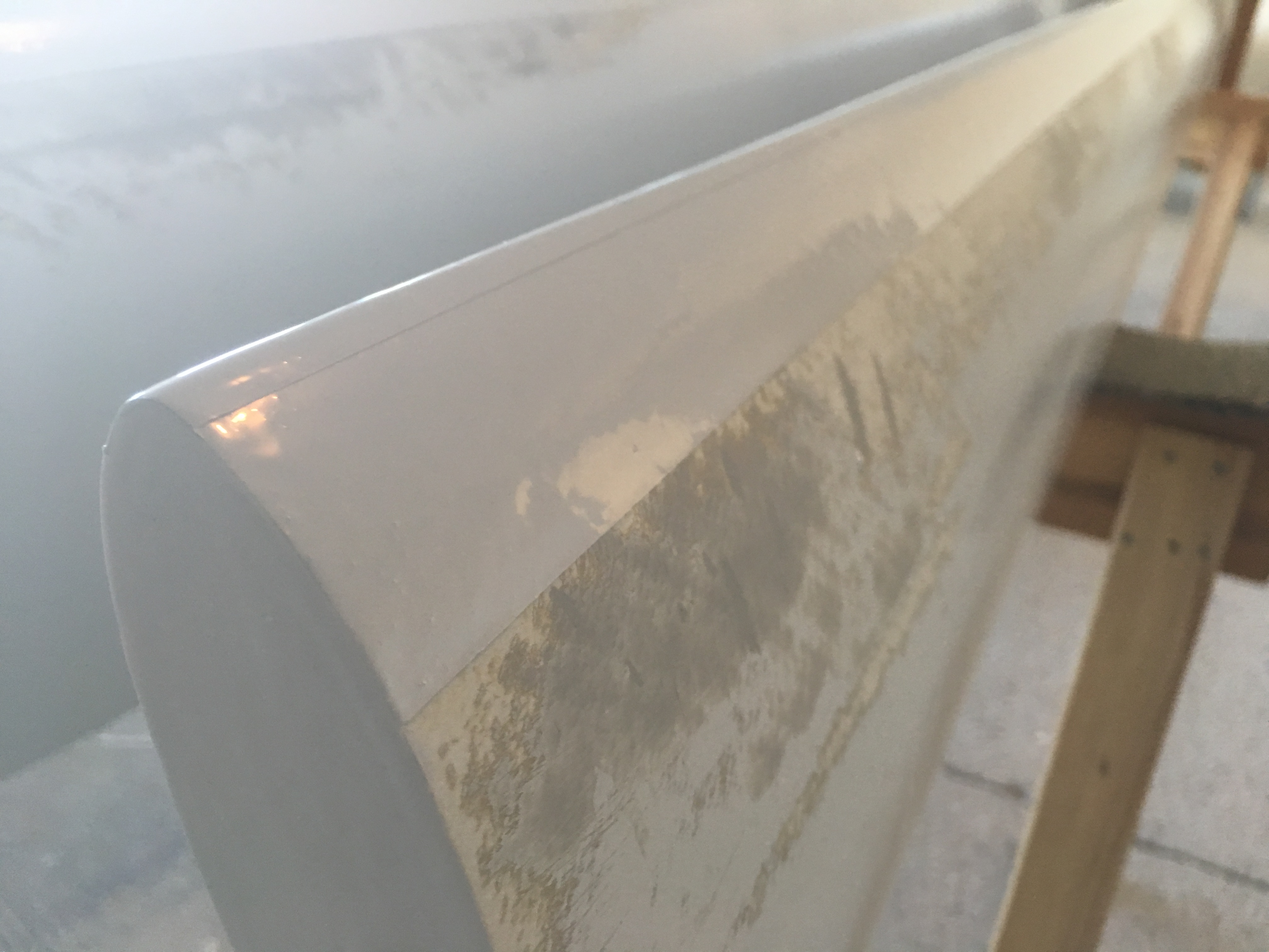
I’ll attach before-and-after pix of my leading edge erosion damage and repair. The repair pics show just the leading edge repair using Duromar WE-9200 filler, and then WE-9300 Leading Edge Protection epoxy paint to replace the leading edge tape that wore away and allowed the blades to be eaten away.! You can see a second layer of L.E.P. epoxy paint in a very narrow strip on the exact leading edge where the erosion was concentrated. The remaining rough areas are from sanding, and will be covered with polyurethane paint, as soon as I get around to finishing the job.
This is what real wind energy is like. Not sitting around all day playing with equations. And by the way, these blades are pultruded fiberglass, constant chord, constant pitch (pigs with high-performance airfoils), not laid-up with a taper and a twist like most blades. They are way heavier than they should be, working on brute force rather than finesse, and are about as big as you can get and still get away with such a brute-force design - no finesse, just very strong. Even so, these Bergey machines can explode in strong winds and throw these heavy blades up to 700 feet. Yikes! (Overspeed protection, it’s not the main thing…)