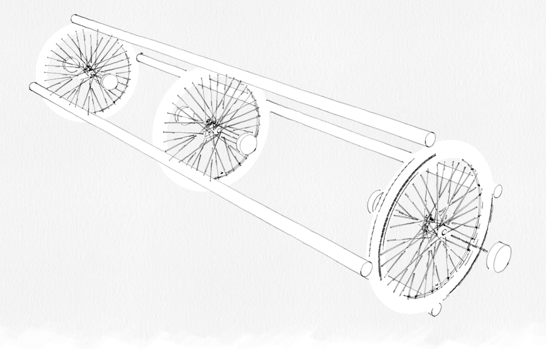
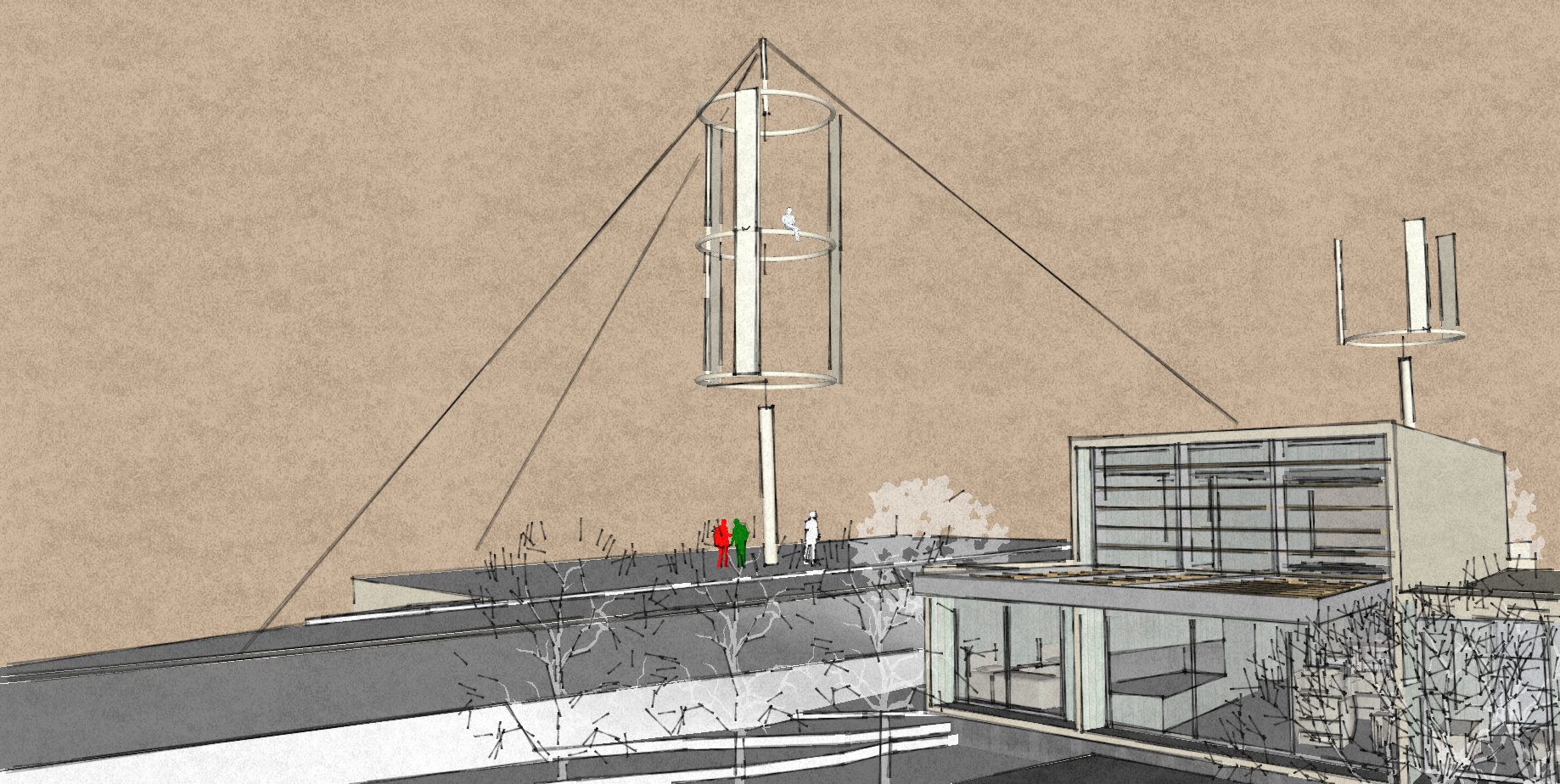
Imagine the bicycle wheels and the rods are tensairity tubes, and the rods have an appropriate blade shape, and it is bigger than the bicycle wheels imply. It is perhaps lifted with a lifter kite, and power is transmitted to the ground with two rope drives from either end of it.
You can also set it right side up and have a more conventional VAWT.
There are 6 disks in the picture, you only need the outer 2 for the rope drive. I didn’t bother to delete the other 4.
This is an idea I had yesterday after considering how I might implement rigidity and torsion in an airborne system. This has a good diameter to length ratio so it should be able to withstand bending and buckling reasonably well I assume. The centrifugal forces are balanced by tethers. The torsion is transmitted to the rope drive in two places instead of one. Analogous to a crosswind system with a Y tether, (tether) drag is only high at the blades.
Looks plausible.
The main issue with this kind of turbine is a smaller swept area per material. Two rope drives add complexity.
If I had to design such a system I would put the axis of rotation on the lifter thether, use flygen with a vane with large lever to counter rotation and increase the diameter. But then it wouldn’t have much to do with your system anymore.
In my view the only reason not to use yo-yo would be to avoid active control and have a passively stable system.
May not be completely bananas if you can find a way to keep the axis in tension.
Like stringing it across a gap somewhere
Nah I don’t think I get it either.
Try it in real life in a model and see how it buckles
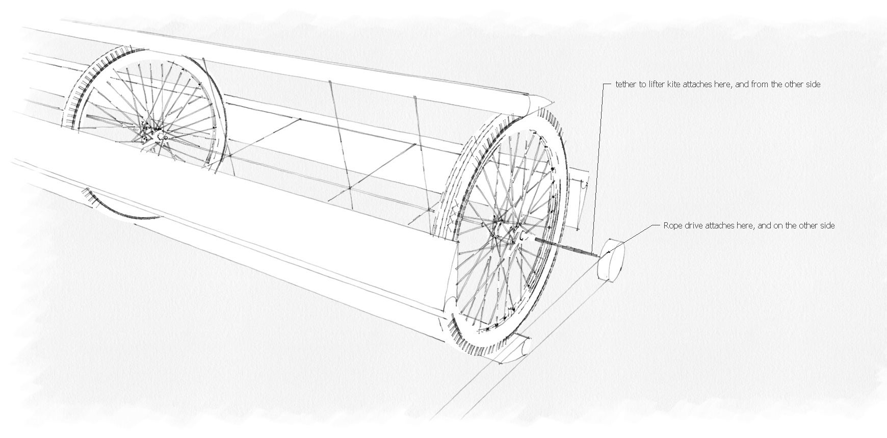
The rigidity should come from the tensairity tubes. The tether from the lifter kite and the rope drive should be close together so bending moment is minimized. And the lifter kite need only have as much lift to lift the system + give some tension to the rope drive - I don’t know how high that tension needs to be.
You mean have it hang vertically from the lifter kite and have a flygen on the bottom of it? That might be easier? The generator would need to be heavy though (to deal with the gear reduction)?
You don’t want it hanging at a 30 degree angle though, maybe there’s a risk of that happening then?
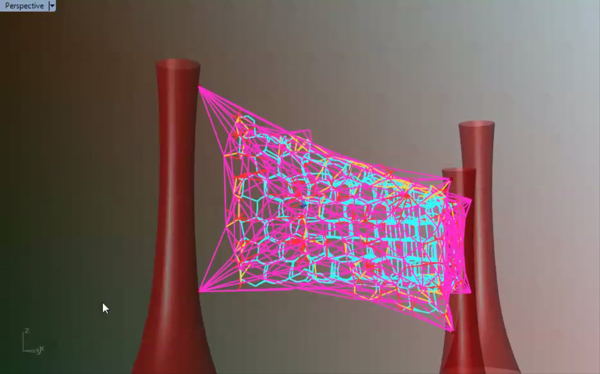
It has similarities to previous and currently investigated designs. Good luck with it if you try. Keen to hear how it might go especially fixed inside a tensile lattice form such as this 6 point lifted 3d lattice net.
The advantage here is you could fit your turbines on any of the light blue lines , so at any time from any direction you’d have 100s or 1000s of well aligned rotors.
I don’t think the turbine you proposed is easy to implement as an airborne wind energy device.
This was a thought experiment in how to transmit torque through a rigid “shaft” in an airborne system. I don’t think airborne systems relying on very long torque transmission are feasible, so I was wondering what systems would perhaps be feasible.
To continue the thought experiment on how to actually develop something, this doesn’t need to be airborne to work, so to make it easier, just set it on the ground (for now):
This then just becomes a Vertical Axis Wind Turbine (VAWT). That has drawbacks and advantages compared to HAWTs, mainly drawbacks: https://en.wikipedia.org/wiki/Darrieus_wind_turbine These have a maximum tested efficiency of around 35 percent.
tensairity tubes are the enabling technology for this, try to make some, and test to destruction.
find an airfoil/turbine shape to copy (humpback whale fins work at more angles of attack?)
If you do it right, maybe the only unknown is how the tensairity tubes will behave, and how you should make them. That just needs time, new insights, and testing, not so much money for materials.
I would say other more «AWE» like systems seem more interesting if you had spare time. This looks to me like a normal windmill, except Im sure less efficient. The swept area is limited as its not travelling mostly crosswind, and this fact makes your wings more or less inert half of the time
This post is focusing on the pros, feel free to focus on the cons, or anything else.
Max efficiency seems to be around 35 percent. Assume around half of that after a few iterations to get 20 percent. That’s close to the efficiency of small HAWTs, that get around 30 percent. You seem to trade efficiency for an easier to make product.
“Interesting” has a few meanings. If you mean this isn’t challenging, I’ll say that’s a good thing. If you mean this doesn’t have much potential, that would be bad. We can’t see the potential yet, though, two days into thinking about it. Now I am thinking this is at least an excellent research platform for developing tensairity tubes. At the end of your research you’d have the experience to make very light, strong, fatigue resistant, and cheap, building elements, hopefully.
The only challenge here is hopefully in how to make the tensairity tubes.
It would be a good research platform because a VAWT is perhaps the simplest type of wind turbine that allows you to submit the tubes to continuous testing outside, unlike airborne systems where you first have to develop the airborne system, that only eventually would fly, very intermittently, and it might be better than a HAWT because this design doesn’t have very long unsupported sections, lowering the chance of failure. Maybe a HAWT with a rim around it (to deal with the stresses) would be more interesting?
When you make something new, you go through an endless cycle of first imagining things, then trying to disprove them. We’re going through that here, I am imagining something, and then try to disprove them with your help. So yes, we can see that here in action.
I think there are better things to do, concepts to follow with your time.
First you need to know what your actual goal is. Then properly evaluate all possible choices. Following a random concept just because it is possible is very unlikely to give you the best outcome.
At this point I don’t think there is much of a point in trying to compete in the commercial space without massive support from a corporation or at least an academic group which is involved in the field.
I gave you my opinion but I will not be the one to say if this is a good or bad concept at this point. My reflections were based on the fact that your blades are going approx half of the time either downwind or upwind, at which times they are bot working at crosswind, where I believe the potential of AWE lies. So if you start from this point, you are a bit handicapped compared to a traditional windmill or any of the more popular AWE concepts. There might be hidden gems here though, who knows.
I think at this time a lot has been said about AWE. I feel the challenge right now should be focused on getting something to actually work over time, at a reasonable price.