The circular flight pattern achieves the highest cycle-averaged power output in a smaller operational area, making it advantageous for maximising energy within limited spatial constraints. Conversely, the figure-of-eight down-loop pattern demonstrates superior power quality with lower power peaks and lower expected structural fatigue due to a reduced cyclic aerodynamic load frequency and amplitude, supporting greater operational stability and system longevity.
Some landmarks in this publication are mentioned below.
From the Introduction:
The MegAWES 3 MW fixed-wing reference kite (Eijkelhof and Schmehl, 2022) is used in conjunction with the new improved flight controller developed by Rossi (2023).
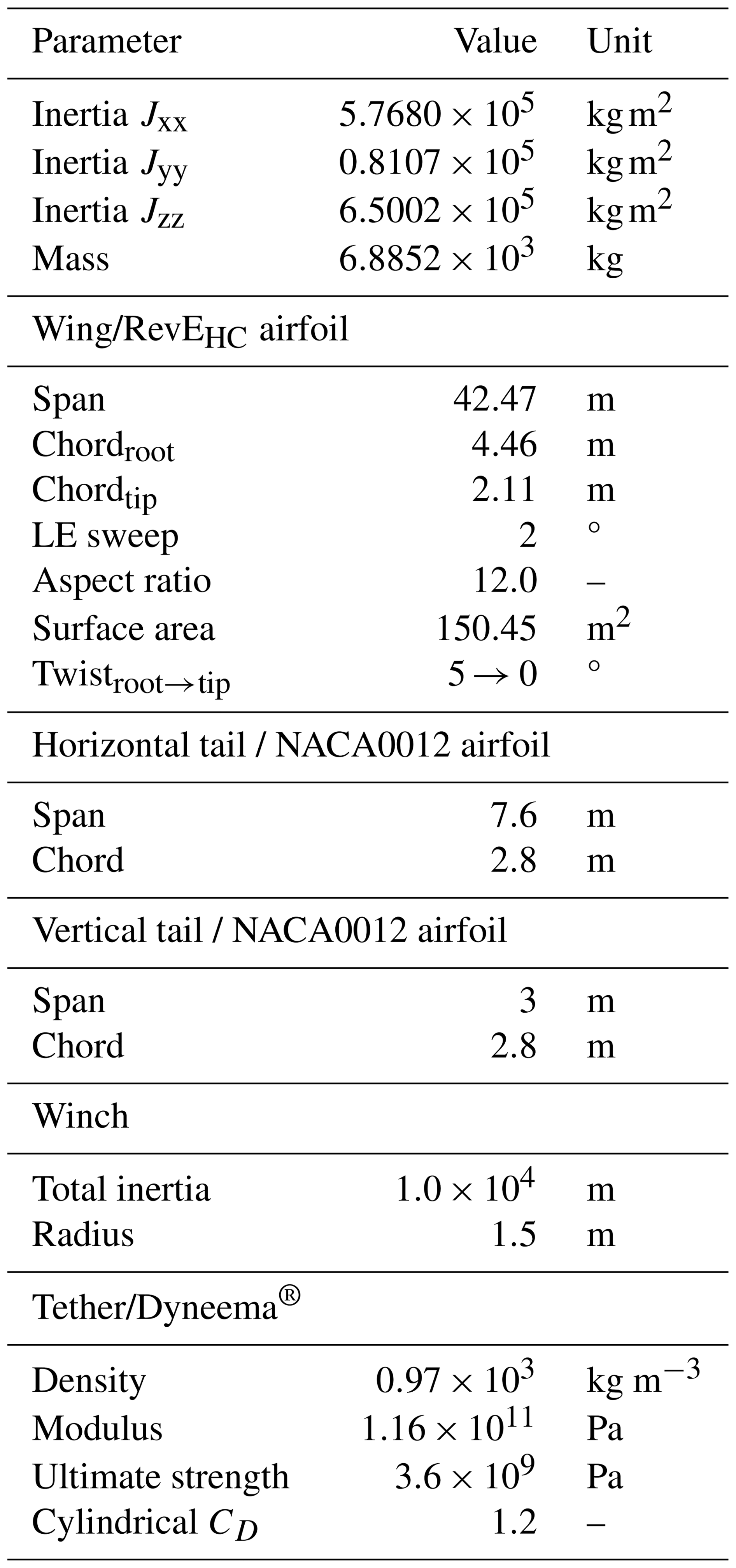
Table 2 General planform parameters of the wing, tail, and fuselage and characteristics of the winch and tether, adapted from Eijkelhof and Schmehl (2022).
3 Results
[…] The simulations are performed in a consistent operational environment at a wind speed of 12 and 15 m s−1 across all tests. These wind speeds are below the rated wind speed. Above the rated wind speed, a real-world kite system is limited to not exceeding the rated power. This limit is not included in this simulation framework. […]
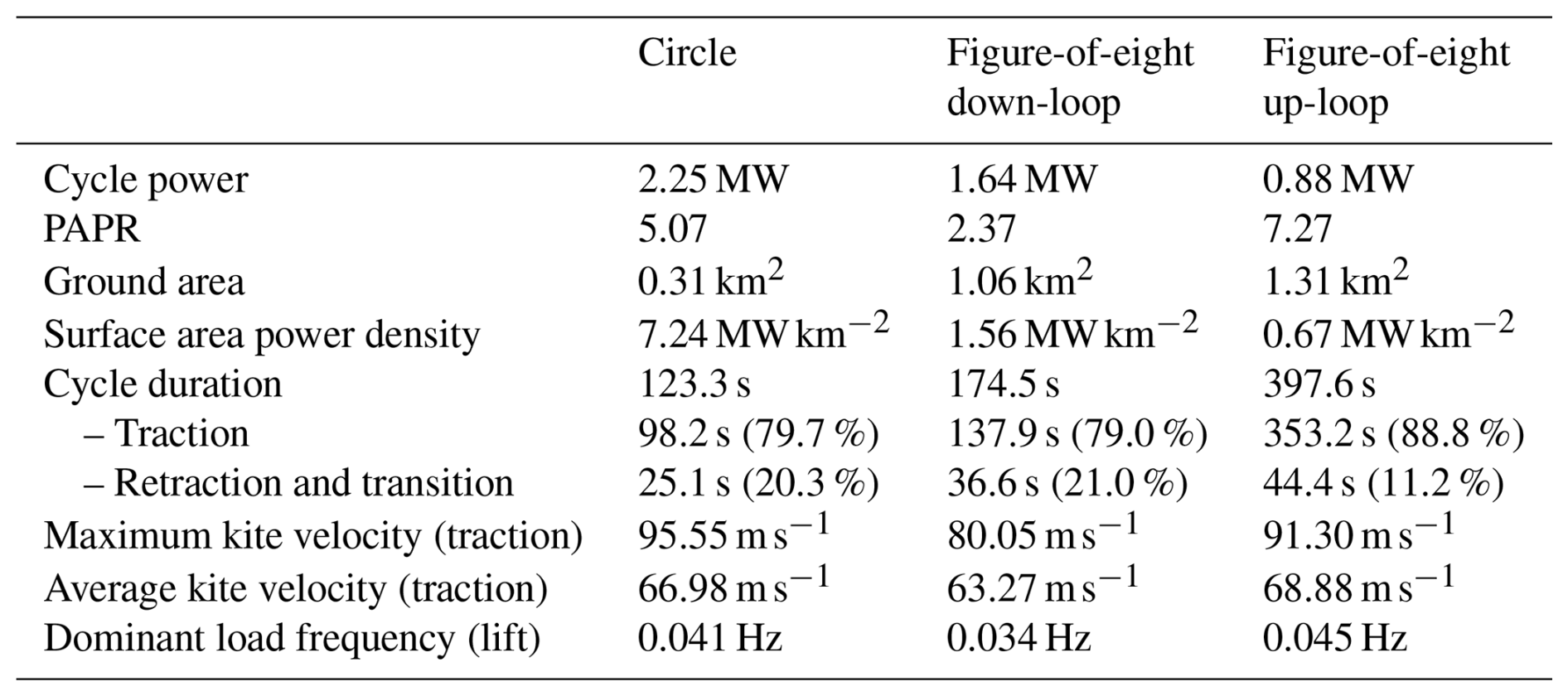
Table 3 Summary of pattern performance of the three studied flight patterns using the MegAWES kite at 15 m s−1 wind speed with active PAPR constraint.
With these points established, I would like to linger a little on the points mentioned in 2.1.2 (equation (3)), then in 2.3:
From 2.1.2 (about equation 3):
[…] where m is the kite mass, Fg is the gravitational force acting on the kite, ϕτ,act is the actual roll angle, FL is the lift force, and ac is the lateral acceleration needed for the vehicle to trace a curved trajectory.
From 2.3:
The power quality is quantified using the peak-to-average-power ratio (PAPR) during the traction phase. It is defined as the ratio between the maximum instantaneous mechanical power and the average power over the traction interval: […]
Is the following point observed in Paula Echeverri’s article on Makani taken into account?
I observed also, as a possible issue connected to the previous one mentioned:
It seems to me that “the maximum instantaneous mechanical power” (from the publication) does not take “potential energy swings” into account.
As a result, perhaps that “superior power quality” of figure-of-eight would also lead to a higher average power, but it is not sure.
In my opinion, there are too many parameters to really guess the performance of large kites, and to make a valid comparison between circular and figure-eight.
I would like to see the measured (and not simulated) real power (if any) of a 7 ton and 42 m winspan kite, circular or figure-eight trajectories, with 15 m/s wind speed.
It seems like a good idea would be to tie a bunch of these kites together in a circular path arrangement so that you could get the benefit of smoothed output and higher power density
In other words, a rotor in the broad sense, including several kites placed at a distance in opposition (MAWES), or blades. And I agree, because a rotor makes it possible to compensate for the imbalances and variations of velocity and power of a single wing, by maintaining a constant speed (depending only on the wind speed).