A Rotating Guyed (Wind Turbine) Tower Concept

There was a recent discussion on making wind turbine towers. Here is my submission.

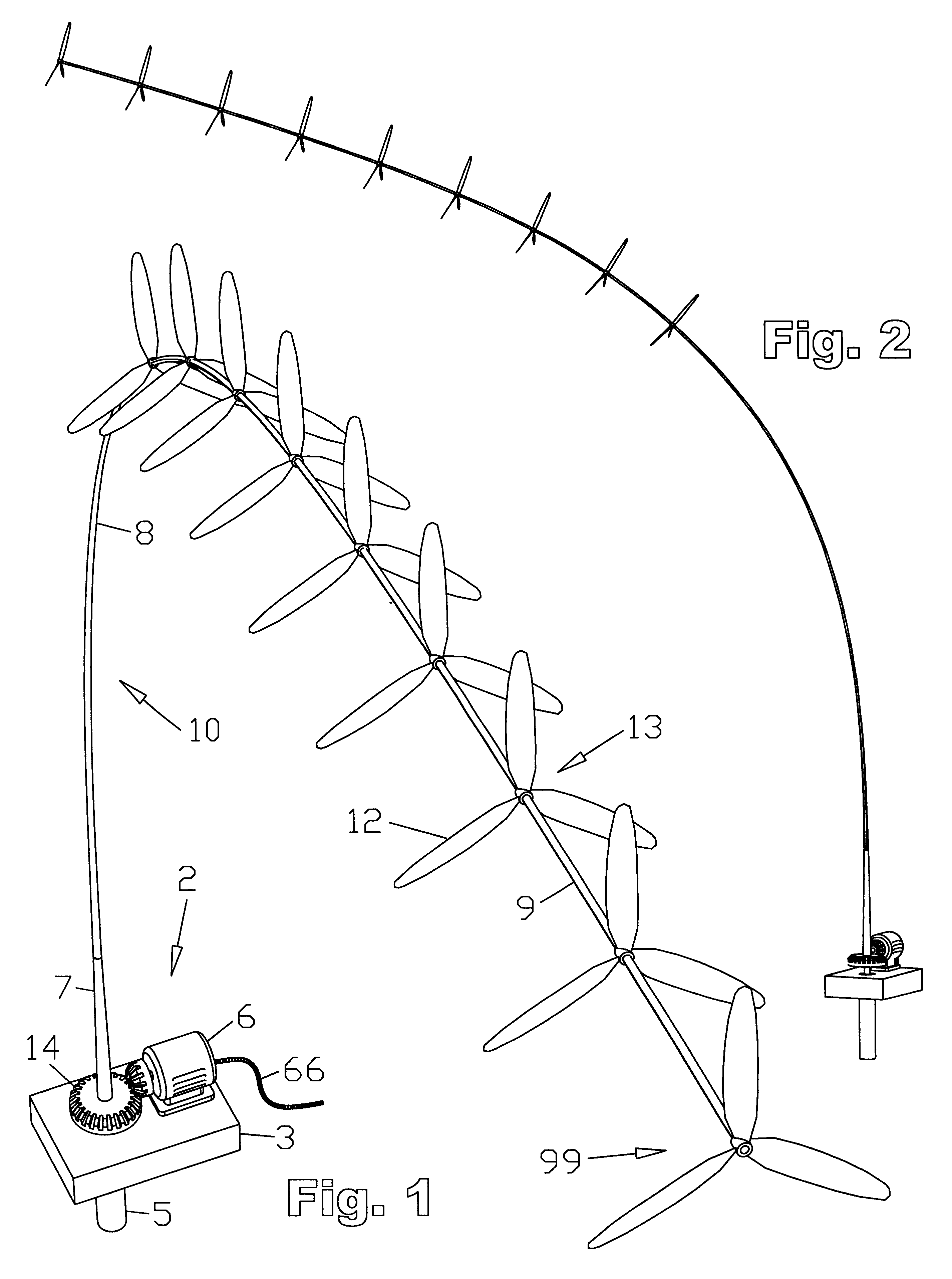
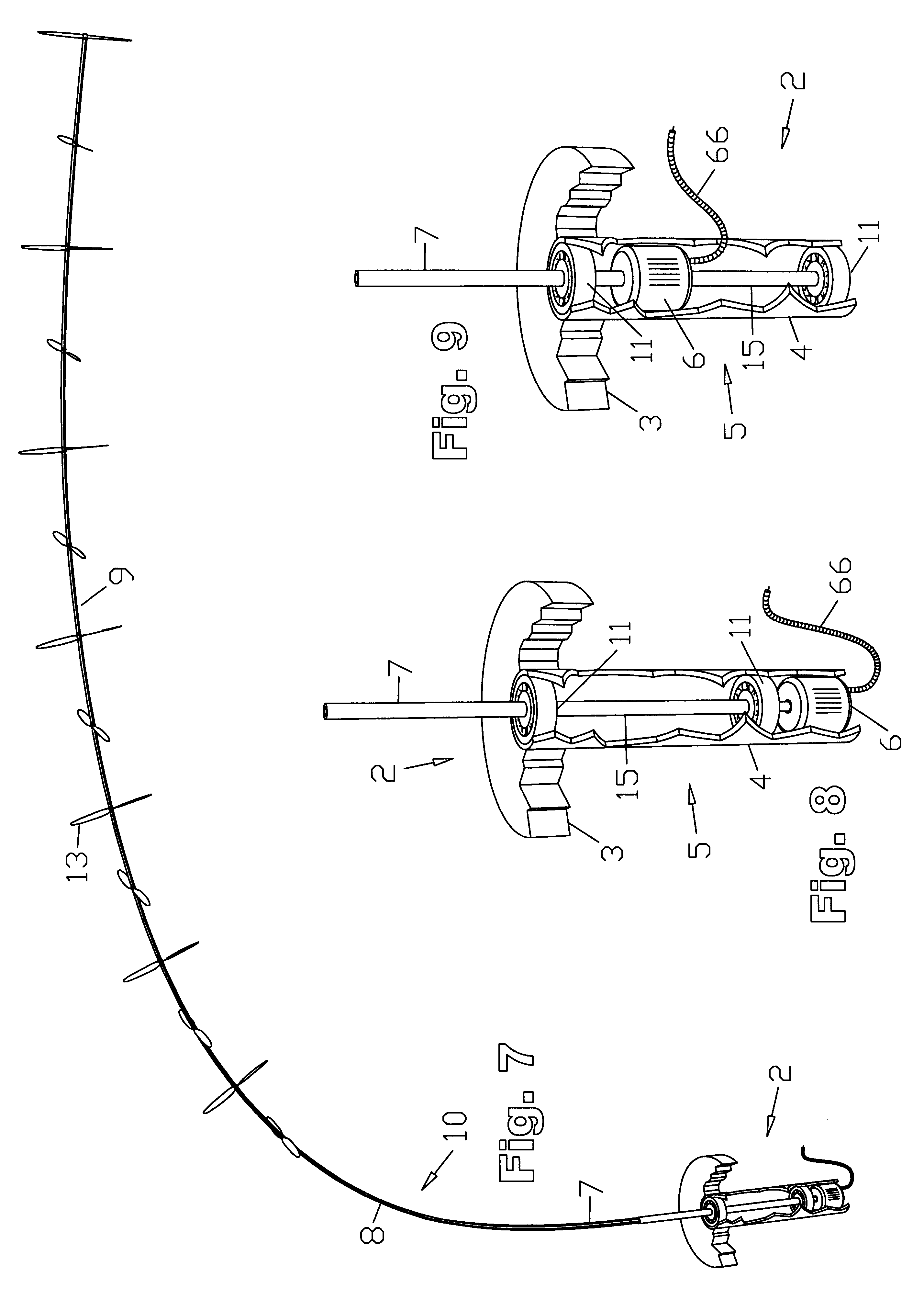
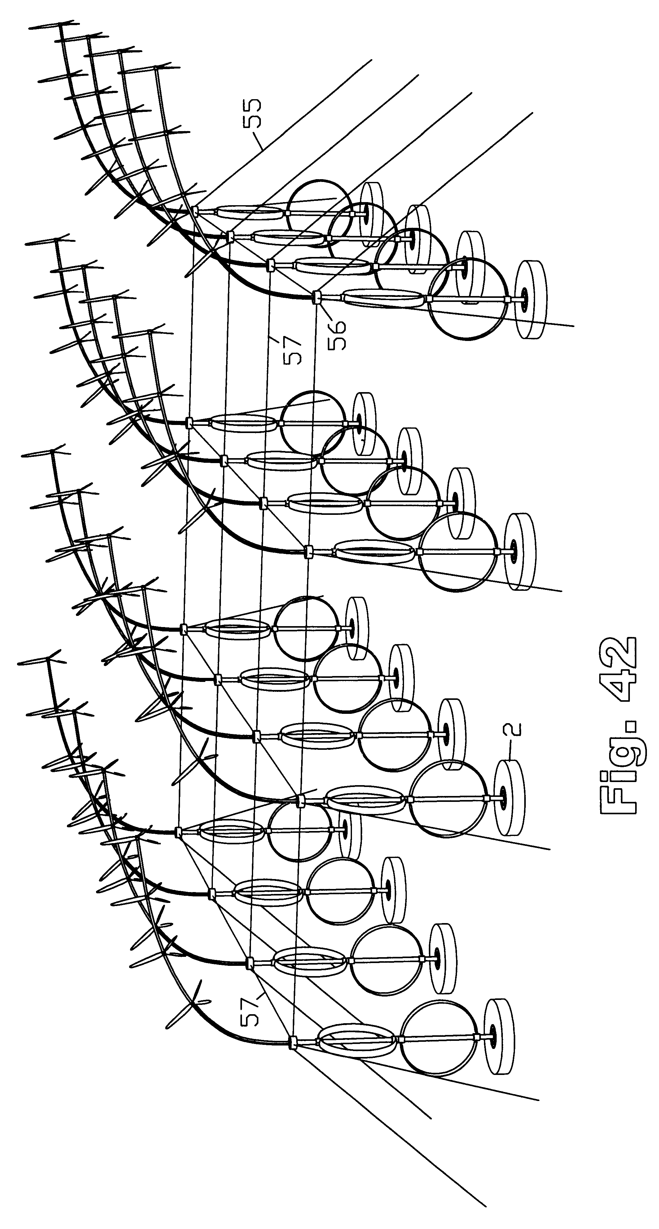
Let’s imagine a symmetrical airfoil as a wind turbine tower. To relieve stress on the base bearing and tower, guy cables ride along circular tracks that get added to the tower at certain heights. This is the novel concept.

Let’s construct the tower out of wood like Modvion does, using the same construction techniques.

I think it makes sense to use a downwind rotor to act as an additional vane and to lower its stiffness requirements. This rotor could potentially be partly tensile, or airborne.

Benefits would be:

  • As a wind turbine tower is loaded mostly in line with the wind from the wind loading on the tower (which here is reduced by an order of magnitude) and the pull from the rotor, this design allows you to make it stronger (wider) in that direction.
  • Upwind wind turbine blades need to be made very stiff to prevent tower strikes, and downwind rotors suffer from the tower wake, this design solves or reduces both problems.
  • No, or reduced, need for a motor to rotate the tower relative to the wind as the airfoil profile of the tower acts as a vane.
  • The, I think, novel concept of guy wires riding along circular rails lowers the strength requirements on the base and the tower.
  • It could be possible, with the added strength in one direction of the tower, to assemble it horizontally, together with the nacelle and blades, and hoist it vertical for installation, or lower it for maintenance.
2 Likes

For the tower to act as a vane, the pivot point would need to be towards the front of the airfoil. Here the pivot point is most likely in the center of the airfoil.


One way you could have the tower act as a vane is by making it slant back from vertical. But that could introduce more problems than it solves. Adding a vane or a motor that rotates the tower seems like the better solution.

So you are thinking that the tower is a airfoil with chord x and a ring surrounds it eg with diameter 5x. Then guying wires on the ring.

So I am a bit confused what we are trying to do here:

  • Is the tower rotating inside the rings, and the rings non moving?
  • Why do we want the tower to be an airfoil shape?

Could we easier take a traditional tower and put some fairing on it, then rotate the fairing?

The problem I am seeing solved here is the removal of the yaw motor. But I am not sure I would prefer all of this to a yawing motor at the nacelle.

Again, classic HAWTs are a bit outside mye expertice. In the sense I probably know equally much about them and AWE, but the field of HAWTs is much more developed and mature. I could not say which parts of a wind turbine that may be most ripe for innovation.

1 Like

I’m thinking an airfoil with chord x, and rings at discrete points along its height of diameter around x also. The tower and rings are fixed to each other and rotate with the help of vanes, and perhaps a backup yawing motor. Guy cables get attached to carriages that ride inside a track on the outside of the rings.

To visualize, if you were to look at the tower from a distance, if you were directly upwind, you’d see a thin tower with a few horizontal disks sticking out of it which had guy cables attached to them. If you were to look at it from the side, you’d see a fat tower where the disks don’t stick out anymore.

You want the tower to be an airfoil shape to reduce the tower wake and wind loading on the tower by an order of magnitude. And if you use an airfoil with a reasonable thickness ratio, you can greatly increase its moment of inertia and with that its resistance to bending from the lift from the rotor, without increasing its material usage or wake too much. To get the same strength in the direction it matters in a non-rotating tower you would need more material and you would create a much bigger wake.

Playing around with the length, width, and wall thickness of a hollow rectangle, say, I think you can target a moment of inertia and with that a resistance to bending that makes sense.

Rotating fairings wouldn’t give you this increase in strength I think, and I think for now it is an unknown if a tower like that is easier or cheaper to manufacture than this concept.

With a rotating tower of course you also get the option of putting the generator and so on on ground level, I don’t know if that is better, but that would make erecting the tower and maintenance easier.

I don’t know if hoisting the tower vertical makes sense for grid-scale turbines, but you could imagine doing that for smaller turbines, and making your tower strong enough to be able to do that on calm days. That could eliminate the need for a crane, which I imagine would decrease the cost of installation.

Hmm. I was thinking maybe adding a control surface to the trailing edge could give you yawing control but also if that control surface was segmented, it could even out vibrations/waves. Controlling the damping of certain frequencies could maybe allow for a higher tower

1 Like

How does that become possible?

1 Like

I was thinking of this with that: Horst Bendix invention: Tower construction for a wind turbine - the tower rotates and the generator is in the tower base

I think for a belt or rope drive the generator needs to fixed relative to the rotor, so this makes that possible.

Right this moment I can’t picture if using a shaft is possible also when the rotor and generator do rotate relative to each other. If it is, putting the generator at ground level was perhaps always a possibility, but I imagine a belt or rope drive makes more sense.


1 Like