A self-erecting passive Daisy (or other rotary)

I had some nice conversations during AWEC, and also some of the talks got me thinking. I believe the “Daisy” windmill might be able to self-erect even without the lifter at the top. I am thinking some particular design may be necessary to achieve this, but in principle, the more advanced “Daisy” setups could already be self erecting without the lifter kite.

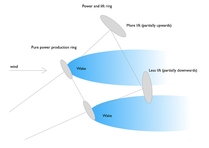
The important thing (sorry if I am stating things that are already obvious to you other guys) is that you have several rotating power generating wing layers, and these layers generate a wake. Because the rotating windmill is not pointing downwind, but rather at an angle upwards, the wake will not hit the next ring at the center of rotation. We can use this fact to make the upper wings in the next ring point more upwards. As they are seeing more wind energy, they will create more vertical lift compared to the lower part of the ring.

The explanation sucks, I have added a sketch to possibly make my point easier to understand.

Another observation is that due to this, the tension at the lower half of the rotating torque transfer matter will experience maybe significantly less tension compared to the upper part. This may be a start of inducing oscillations to the system. Sorry :slight_smile:

@rodread @someAWE_cb

2 Likes

Like it!
Yes, but if the blades are banked the lower wings have a larger surface presented to the real wind direction… So they may have more tension.
Also… With using a lifter, there is already more tension on the lower lines.

Are you suggesting a cyclic change in the wings? It could imply quite a lot of energy expenditure and wear.

If we disregard wind, just keep the rig rotating (lets assume it is powered from the ground), I think we can agree that the top and bottom wing are seeing the same lift, and if we dont consider gravity, the rig is perfectly balanced and thus stationary (but not stable).

Lets say the wings are tilted \alpha degrees outwards, with \alpha = 0 being the wings placed in the rotating plane. The elevation angle is \theta. The wing area is s.

Next lets simplify and consider just the wing at top and bottom of the loop. Both of these are moving only crosswind.

The area of the top and bottom wing facing the wind would be approximately s \cos \left(\theta + \alpha \right) for the top wing and s \cos \left(\theta - \alpha \right) for the bottom wing.

It is true that this would mean almost an linear increase in lifting power and thus pull the rig towards the ground

The effect of the wake would have to be larger than this effect. I guess there is no answering this without some simulation work or at least some experience with wakes

Still, lets make some quick estimates. If \alpha = 10\deg and \theta = 30\deg, the difference in projected area is 23%. If we extract 20% of the wind energy to create the wake, the difference in wind speed would be just 6% (energy proportional to wind speed to the power of three), and this would be a change in force of 12%.

So it seems the value of \alpha must be quite small, the extraction of wind energy must be really high and masses low in order for this to work.

One could increase the wind energy extraction by adding solitidy to the power gen ring (more kite wing area by adding more kites)

OR

Just use negative \alpha and dont rely on the wake. Use centrifugal forces to keep the kites separated.

Probably a daft idea both ways

I was thinking passive control as in no electronics. But adding electric roll control would probably be a simple means to keep the rig upright. But then you wouldnt need to consider all this

There are suggestions of methods to expand coilable mast structures with torque transmission capability in this work
https://www.researchgate.net/publication/312217080_Advanced_Deployable_Structural_Systems_for_Small_Satellites
So a rotary kite turbine might be deploy-able without powering the rig around for launch

I’m really impressed with the summary of
OVERVIEW OF HIGHLY FLEXIBLE, DEPLOYABLE
LATTICE STRUCTURES USED IN ARCHITECTURE
AND CIVIL ENGINEERING UNDERGOING LARGE
DISPLACEMENTS
Noemi Friedman1,2, Adnan Ibrahimbegovic3

  1. SUMMARY
    In order to give a general survey, several deployable lattice designs were presented, that
    offer possibilities in architectural applications. Deployable structures can be created from
    mechanisms that can be controlled by pneumatic systems, cables or other actuators. Tensegrity
    structures, which are in the first place applied for sculptures have the intrinsic possibility to
    be deployable. The main advantage of tensegrities is the simplicity of joints as only tendons
    are connected to struts in accordance with the canonical definition. However, the analysis
    of deployable tensegrities is extremely cumbersome; it involves highly nonlinear analysis due
    to prestressed cables with nonsmooth, unilateral constitutive model, finite displacement
    simulation, contact problems for eliminating intersection of elements during deployment etc.
    A large number of deployable structures use pantographic systems. Though the scissor joint
    of the basic element is easy to construct, the further connection of the SLEs requires spherical
    joints. Furthermore, the simplest scissor joint construction evolves often non negligible friction
    effects. Pantographic systems can be combined with sliding joints, too, like some cable and strut
    systems.
    If the mechanism is such that the degree of freedom of motion is only one, the control of the
    structure can be simple and fast. However, there is a trend to apply transformable structures not
    only to create a fast constructional method but to design morph shaping architectural structures
    to adapt the building to changing occupant demands and for reducing environmental impact
    and for a better energy efficiency. Morph-shaping structures are currently one of the most
    prospective research topic of civil engineering structures. In fact, simple control of such
    systems is of high complexity, a highly distributive, intelligent control and sensor system can
    completely transform the today’s urban architecture to a dynamic, more economical, and less
    intrusive environment.
    The second category of deployable structures is the snap-through type structures. These
    systems are either self-deploying or self-locking systems, depending on the stability of the
    equilibrium state in the packed configuration. While the self-locking system is stable and stressfree in the packed configuration, the pop-up structures are in an unstable equilibrium state in
    their compact configuration, corresponding to the maximum of the stored strain energy. This
    state enables the structure to dynamically self-deploy. The main advantage of these structures
    is that no additional stabilizing element is needed that makes the construction extremely rapid.
    The major problems of self-locking and self-deploying systems is that omitting additional poststiffening often results in the lack of sufficient structural stiffness or the occurrence of massive
    deploying stresses during deployment/packing. Furthermore, the complexity of analysis is of
    high order due to the non negligible inertial effects occurring at snapping of the structure.
    In this article it was shown that already a great deal of different transformable systems are
    invented, however, it would be inadequate to say that application possibilities in the field of civil
    engineering and architecture are already well established. The difficulty arouses from either the
    Unauthenticated
    Download Date | 1/7/20 11:19 AM
    YBL JOURNAL OF BUILT ENVIRONMENT Vol. 1 Issue 1 (2013) 101
    need of complex and cumbersome fabrication process (in the case of a larger scale structure) or
    in other cases the problem comes from the necessary highly nonlinear analysis of these flexible
    systems. The (very briefly) presented examples show that even the analysis of a single basic
    element can be cumbersome and may require profound understanding of nonlinear behavior.
    When analyzing the interconnected single elements together the complexity of the simulation
    become even of higher order. Possibly the biggest challenge is that unlikely to conventional
    structures the inertial effects during the transformation process, as well as the uncertain energy
    absorptions, are of high importance in general and consequently cannot be ignored in the
    analysis. The architectural design work for individual applications, the elaborating calculation
    process and the lack of standardizable procedure for dynamical calculation and the necessary
    calculation costs will possibly keep the artists, the architects and the engineers busy for a while.
    At least the ones that have a hunger to feed their mind. Eventually and hopefully, combining
    transformable structures with a highly distributed control system which is already available in
    today’s technology an intelligent responsive architecture will be born