Can a wind plant compete with a gas plant? Trying with a VAWT carousel with vertical blades.

The current storage is far from sufficient. The backup is made by fossil fuels, mainly gas. As a result, taking the example of Germany, CO2 emissions have continued to increase since the abandonment of nuclear power.

It is beginning to be known, and wind power is stabilizing (not increasing) in the world now at a very low level.

Data on

1 Like

Yes, classically the intermittence of wind is why it can never take over from dispatchable sources such as coal or natgas. Windy_Skies says “Just add storage”. Typical response whenever laymen discuss such things as providing reliable energy. “Just” do this, “just.” do that. Here is the problem: Energy “storage” requires UN-generating power, then RE-generating that same storage. So instead of just generating power while it is being used, you have to:

  1. Generate the power
  2. UN-generate the power
  3. RE-generate the power
    Which logically will end up costing, say, three times as much as just using it while you make it. “Storage” sounds good, like you just put it in your closet or something, but in real life it costs big money. Off-grid people know just their battery bank costs way more than using grid power. That does not include the cost of wherever the power comes from - solar panels, wind turbine, whatever. The batteries require constant maintenance, temperature control, etc., then they have a finite lifetime, number of charge-discharge cycles, etc. before they must be replaced. If these questions were so simple to answer, we would not have a constant “energy crisis” going on for most of my lifetime so far and counting. One thing to keep in mind: The “green” movement is sponsored by the oil companies, whose main way to keep prices high is restricting drilling by newcomers, which means funding environmental causes to the extent they can be used to rationalize drilling restrictions legislated in response to lobbyists hired by the causes they fund. It is a case of “Brer Rabbit” who pleads “Don’t throw me into the briar patch!” when really he knows it will help him. Same with big oil. It’s called controlled opposition. The last thing they want is small players able to drill for oil everywhere, so they make sure it can’t happen. Artificial “scarcity” keeps prices high.

Thanks @dougselsam and @tallakt for their contributions. Efficient innovation remains difficult in the field of wind energy.

Hi Pierre:
Yup it is like a trap for the unwary, a deep hole covered with thin branches and debris, looking like solid ground as a disguise, so the innocent will see it as simple, solid ground, easy to understand, easy to walk all over without worry. 'Til the “solid ground” they thought they understood gives way, and they fall in, never to resurface.
Or maybe a casino or carnival game where it is set up for you to lose a lot of money trying to win, maybe coming away with a stuffed animal to parade around the fairgrounds or casino floor for a short time, if you are one of the lucky players. :slight_smile:

Below are some information from the engineer Guy Mercer, author of the concept discussed on the current topic:

Dear Pierre Benhaiem,

You may publish these answers if you wish.

You are correct in that the giant VAWT will have a much greater power / Km^2 than any HAWT farm. But it will also be greater than a farm of traditional sized VAWTs. In part due to the vertical height which is captured but also the efficiency of the aerofoils for 2 reasons:

  1. With a large diameter the chord of the aerofoils can be increased which increases the Reynolds number.

This has the effect of increasing the lift to drag ratio and the absolute coefficient of lift.

That results in much greater tangential force (per unit aerofoil area) magnifying the power output.

  1. The large diameter reduces the speed of rotation ( for a given TSR ) which decreases the rate of change of the apparent wind to the tangent. This enables wind velocity sensitive, aerodynamic balance to be used to control the AOA ( angle of attack).

The ability of the aerofoil to automatically pitch protects the system in extreme weather conditions but from initial spread sheet calculations it also increases the power output by 11% compared to using fixed aerofoils.

Note I have not added in the 11% since I used Qblade for simulation, which does not include a pitching facility.

It may be possible to increase the power further using full servo driven pitch control, but the additional cost and maintenance requirements may not be justified.

Friction:

It is not possible to avoid friction, but it can be minimized or used to advantage:

In an offshore version it is ideal to take advantage of the friction creating a link between the turbine and the water, such that the water becomes an integral part of the system acting as a massive flywheel. I have attached a simply example of Couette flow analysis showing an example of water drag on the flywheel.

Because the amount of energy that can be stored kinetically is so large it makes it possible to store energy from strong winds while still generating at maximum capacity and use that energy to supplement the power of lighter winds potentially increasing the annual generating capacity by around 25%.

Safety in the harshest of marine environment:

My initial thought was for a continuous hull with a trapped air curtain about 1 metre thick under it fed from a small compressor operating at around 1 Bar. Such a system would displace up to 10 metres of water but have lower friction due to the air cushion.

This is valid option for an onshore version but as mentioned in the maxwindpower.com site:

For the offshore version: The ring which supports the aerofoils can be a skeletal structure, made in sections and of neutral buoyancy, mainly several metres below the water line with ” conning towers / floats ” above water and on which the aerofoils are mounted to ensure they are well clear of any storm / freak waves. This achieves 3 things: (1) Boat access to the generating hub. (2) Very little stress on the support structure due to waves as most is below the water. (3) The support structure and the links to the hub create a friction link to the water. The structure and the water become a giant flywheel of millions of tonnes storing multi GWh of energy. As with any battery / flywheel there are losses but Couette flow analysis indicates that this is relatively minimal.

In that manner it is quite easy to ensure that the bottom of any aerofoil is at least 40 metres above the nominal sea level.

Kind Regards

Guy Mercer

Water drag on floating flywheel of a giant VAWT .

PCD of aerofoils = 2500 m
Tip Speed = 25 m/s
overall diameter D= 2600 m Radius R = 1300 m
Displacement depth d = 10 m
Water depth = 62 m Depth under rim H = 62 – 10 = 52 m

Tangential velocity of OD U = 25 x 2600 / 2500 = 26 m/s

Consider spokes creating rotating plane flush with bottom of rim.
Consider cone of tethers creating stationary surface with cone extending to OD.
Consider a stationary wall same distance out as the depth under the rim.

The shear rate Y= U / H =26 / 52 = 0.5 /s
This applies to all rotating surfaces / planes.

Dynamic viscosity of water N = 0.001Ns/m^2

Shearing Stress T = N xY = 0.001 x 0.5 = 0.0005 N/m^2

On the Underside the power required at a radius (r) is T x (2 x Pi x r x dr) x (U x r / R)
which can be integrated between the limits of 0 to R to give T x 2 x Pi x U x R^2 / 3
Underside Power required = 0.0005 x 2 x 3.1416 x 26 x 1300^2 / 3 Nm/s
= 46014 watts

On the OD of Rim power required = T x Pi x D x d x U
= 0.0005 x 3.1416 x 2600 x 10 x 26 Nm/s
= 1062 watts
Total power required = 47076 watts = Less than 50 KW

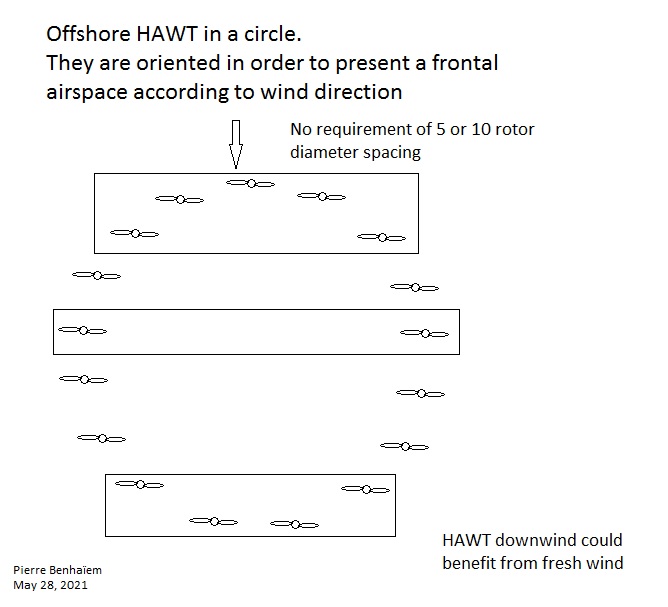
Let us leave aside the flywheel effect. A perhaps simpler way to save space would be to install a circle of HAWT wind turbines at sea. Part of said wind turbines being in the direction of the wind would operate. Some downwind HAWT could also work if the circle is large enough compared to turbine height. Such an installation would allow to remove the requirement of 5 to 10 times the rotor diameter spacing in all directions between two HAWT.

The first assumption or claim is that there is a need to save space. Can you give some figures to back that up? How much is the lack of space costing the wind industry, or other stake holders? You can then start to compare that cost with the costs of interventions and see if your interventions might make sense.

An example of the problem of the space occupied by wind turbine farms:
https://www.ans.org/news/article-933/wind-nuclear-infographic/

Optimally, wind turbines should be placed at least 7-15 diameter widths apart.

Not too far from:

You can learn about basic problems of energies then give your opinion.

It only states that wind farms occupy land. It doesn’t quantify the costs of that. It also isn’t about offshore wind, which is I think where most development is nowadays.

My opinion is on how to compare solutions: you start with the costs associated with the current situation and compare that with your proposed solution. It’s one of the first questions anyone should ask.

No. Please before replying take tour time to read the link I mentioned, and also read carefully what I wrote.

Yes.

The link doesn’t answer my questions above. Also it is outdated.

I’ll ask you to carefully read what I wrote above. I’m being reasonably precise I think.

This idea of yours has the benefit of it just being rearrangements of wind turbines compared to convention, so it should be more straightforward to compare the costs of doing it like this. I’m not asking for the cost of your first proposed solution in this thread, and others like it, because there are too many unknowns for those.

It’s a density problem. If the question of cost came naturally from density, you would have had the answer a long time ago.

I’m using precise language. I used the words “give figures” and “quantify”, to put the problem in numbers. A possible answer should have numbers. You could also say that you don’t know or care.

If you carefully read my answers and the link I provided, which is still valid, you would have a quantified answer to the density problem.

I guess that the price per km² to pay would be lower in Antarctica than in Chicago…

I will end this discussion.

Some elements about the costs of offshore wind turbines are on Wind farm costs – Guide to an offshore wind farm.

They don’t include capacity density concern which is another field.

As I mentioned (“It’s a density problem”) the studies about arrangements offshore in this topic include the capacity densities.

1 Like

For the offshore version: The ring which supports the aerofoils can be a skeletal structure, made in sections and of neutral buoyancy, mainly several metres below the water line with ” conning towers / floats ” above water and on which the aerofoils are mounted to ensure they are well clear of any storm / freak waves. This achieves 3 things: (1) Boat access to the generating hub. (2) Very little stress on the support structure due to waves as most is below the water. (3) The support structure and the links to the hub create a friction link to the water. The structure and the water become a giant flywheel of millions of tonnes storing multi GWh of energy. As with any battery / flywheel there are losses but Couette flow analysis indicates that this is relatively minimal.

2 Likes

Welcome to the forum @GuyM.

Thank for your presentation. If necessary, please correct any possible misinterpretations including mine, concerning the system as a whole and the flywheel effect.

1 Like

Thank you for the welcome.
The real advantage of including the flywheel is that energy from winds above the generator’s capacity can be stored kinetically to supplement the power from lighter winds. The more frequent the change in wind speeds the greater the advantage. The cost of a system tends to be relative to generator capacity and the cabling infrastructure. Increasing the annual production by using a flywheel in this manner reduces energy cost but more importantly lowers the lifetime CO2 emission rate per unit of power generated.

What about water friction/drag? This sounds like a broad, sweeping idea, with few details and no numbers behind it.

The losses can be found using Couette flow analysis. I gave PierreB an example which I note he has published with my consent ( 20 May ). Like any storage system there are losses but in this case it is surprisingly minimal. We tend to think of driving a boat or ship through the water rather than allowing the water itself to rotate at different rates depending on depth and position.