Can a wind plant compete with a gas plant? Trying with a VAWT carousel with vertical blades.

Ideas coming from AWE could evolve towards fruitful realizations in current (ground-based) wind energy.

As an example @Massimo conceived for KiteGen a carousel. Using such a carousel, replacing kites with vertical blades in order to achieve scalability in any dimensions towards a better Power to space use ratio, towards a single (here VAWT) wind plant being able to begin to compete with a single gas plant, avoiding the still difficult control of the kites, knowing also that in offshore conditions the wind gradient is low, like the expected benefit of high altitude winds.

I join some documents describing some (not main (imho)) aspects such like the flywheel effect, while evaluating the main (imho) aspect which is the possibility of implementing a single wind plant being not limited by the 15 or 20 MW reachable by a HAWT, being able to scale then achieve a power comparable to that of a gas plant.

An illustration from the document:

Some calculations and comparisons with current HAWT-farms are on:

The power generated per unit area :
VAWT system can be 3.39 x more than HAWT system with 75% generator rating
VAWT system can be 4 x more than HAWT system with Same generator rating

See also a picture of the KiteGen carousel on:
image
from http://www.plef.org/wp-content/uploads/2013/02/KiteGen-Introduzione-Andrea-Papini-V01.pdf.

A project associating a carousel comprising a double option, VAWT with vertical blades, then KiteGen AWE with kites, would maybe boost wind energy.

Question: Can a wind plant compete with a gas plant?
Answer: Yes, but only when a consistently-strong wind is blowing. If there is no wind, then a wind plant can’t compete with anything except solar after sunset.

Wind energy remains an intermittent energy, unlike fossil fuels and nuclear which are controllable, but capacity factor offshore is higher than onshore, being about 30-45%.

Another obstacle of wind power compared to controllable energies is the dispersal of many units in large areas. A HAWT-farm uses only a tiny fraction of the intercepted wind.

This problem is made much worse with AWES and their long tethers going in all directions.

If these obstacles are eventually overcome in one way or another, only intermittency would remain or even be removed by taking account of the flywheel effect for very large carousels.

That could be wrong. Assuming a carousel of 5 miles (8 km) diameter and blades of 1/8 diameter (not more to benefit from a better efficiency in the leeward row), so 1 km height. The weight of the rotor and its speed would lead to a huge moment of inertia. I don’t think such a machine would stop often. A brief calculation would give a power of 2 to 3 GW reduced to one (1) permanent GW, for only 50 km² sea use compared to about 230 Haliads (12 MW each) occupying hundreds of km² and requiring vessels to slalom and maintenance engineers to travel from turbine to turbine. The larger the machine, the more energy it stores.

I must say that the documents that I have attached above draw a perspective such as I have not seen for several years concerning unconventional wind power, even though I don’t know if the “floating flywheel” on “air cushion” solution such as presented may be adequate. If yes, it would be an interesting mass supplement. If no just stick to the mass of the rotor and blades.

Dream on Pierre. :slight_smile:
And storage will be a tougher egg to crack than most people imagine too.
The reason?
“Storing” energy consists of:

  1. generating the energy in the first place
  2. un-generating that same energy
  3. storing that un-generated energy
  4. RE-generating that same energy again, from storage.
    At first glance, that would suggest 3x - 4x the cost of just generating the energy. Not sure if it could realistically get much cheaper than that.
    The only efficient storage is batteries and even then you throw away 10%, but battery storage is too expensive to be large scale.
    A gas plant uses mostly just step 4.

No Doug, a giant carousel is also a giant flywheel due to the huge mass of the rotor and the blades in rotation at good speed. Let it turn, it is all.

No, in a flywheel, energy and rotating speed is correlated. In a windmill, windspeed and rotating speed is correlated. These uses can’t be easily merged. And flywheels are compact and rotate at high speeds. I have not yet heard of a flywheel formed as a large ring, in particular one floating at sea.

Just a quick glance at tolerances required would show that this is pretty difficult even at moderate waves and windspeeds

1 Like

Please before comment read completely the documents I joined, then come back. Thanks.

1 Like

Some general explains are required to understand the principle of a flywheel before going to the subtleties of the documents I joined and I try to discuss above :

As with other types of accumulators, a flywheel inherently smoothes sufficiently small deviations in the power output of a system, thereby effectively playing the role of a low-pass filter with respect to the mechanical velocity (angular, or otherwise) of the system. More precisely, a flywheel’s stored energy will donate a surge in power output upon a drop in power input and will conversely absorb any excess power input (system-generated power) in the form of rotational energy.

For the current VAWT carousel, the flywheel effect allows to smooth out lulls and gusts. The rotational speed will correspond to the wind speed but in average for a long unity of time. The carousel will not accelerate at the first gust, and not slowdown at the first lull. The heavier it is (adding that the masses are placed at the periphery), the greater the inertia will be.

Here there is no transfer of energy from a device towards another device since the VAWT carousel is a flywheel itself and works as such.

A similar use is for gyrocopter where tip blades are weighted in order to smooth the rotation speed.

After reviewing this concept, it seems indeed that the implementation would be very difficult if even possible, much like the AWE carousel. To begin with, it would be necessary to raise the stator ring so the rotor ring …

In the initial document the main mass is assured by a floating ballast containing water. I saw this solution as likely not feasible. As a result only the weight of the structure works as a flywheel-like, leading to smoothing potential of not more than a few tens of minutes or hours at best.

For the rest I do not know what would be lost in the case of using the flywheel effect: an enormous mass would act as a filter not allowing the small variations to pass as I mentioned above.

I end up thinking that the big wind companies have all looked at the various concepts we talk about, including AWE, without going any further.

Regarding AWE this may be normal after all: the railways did not look too much at aviation in its early days, although I think my parallel is questionable.

Just off the top of my head, maybe I don’t understand certain details, but it seems that water friction and drag of a rotating ring of vertical-axis blades, would hamper performance, and prevent any serious energy storage or retrieval by a flywheel effect. A flywheel needs to be as close to frictionless as possible. Supporting the ring on an air cushion? Using miles of what sort of frictionless seals? Sounds like more “all you gotta do is” nonsense. Typical case of presenting an unworkable idea, then adding more unworkable complications to “fix” it. While the ring itself might work, I doubt it could provide much in the way of energy storage. Maybe a slight inertial smoothing effect on instantaneous output fluctuations, but that would be about the max you could expect, in my view.

1 Like

Water friction can occur only if floating water reservoirs are implemented. Beside aerodynamic drag (which is lowered in case of no wind) there is friction of the rotor ring running on the stator ring. Perhaps that could work better even without adding water reservoirs by reducing drastically the nominal power, and so the resulting friction.

The intermittence of wind energy is really a huge problem because variations disturb the grid. So perhaps it can be better to reduce the nominal power in order to provide a more regular energy.

That’s a talking point I’m not sure I agree with. Just add storage and if that isn’t enough just lower your prices enough to kill the competition and the talking point, or vary your prices to guide the consumer to use electricity when you want her to, for example.

And it isn’t a problem for you. Your only challenge is to generate your electricity cheaply enough so that you can make a profit while still being much cheaper than the competition so you can grow your market share.

The current storage is far from sufficient. The backup is made by fossil fuels, mainly gas. As a result, taking the example of Germany, CO2 emissions have continued to increase since the abandonment of nuclear power.

It is beginning to be known, and wind power is stabilizing (not increasing) in the world now at a very low level.

Data on

1 Like

Yes, classically the intermittence of wind is why it can never take over from dispatchable sources such as coal or natgas. Windy_Skies says “Just add storage”. Typical response whenever laymen discuss such things as providing reliable energy. “Just” do this, “just.” do that. Here is the problem: Energy “storage” requires UN-generating power, then RE-generating that same storage. So instead of just generating power while it is being used, you have to:

  1. Generate the power
  2. UN-generate the power
  3. RE-generate the power
    Which logically will end up costing, say, three times as much as just using it while you make it. “Storage” sounds good, like you just put it in your closet or something, but in real life it costs big money. Off-grid people know just their battery bank costs way more than using grid power. That does not include the cost of wherever the power comes from - solar panels, wind turbine, whatever. The batteries require constant maintenance, temperature control, etc., then they have a finite lifetime, number of charge-discharge cycles, etc. before they must be replaced. If these questions were so simple to answer, we would not have a constant “energy crisis” going on for most of my lifetime so far and counting. One thing to keep in mind: The “green” movement is sponsored by the oil companies, whose main way to keep prices high is restricting drilling by newcomers, which means funding environmental causes to the extent they can be used to rationalize drilling restrictions legislated in response to lobbyists hired by the causes they fund. It is a case of “Brer Rabbit” who pleads “Don’t throw me into the briar patch!” when really he knows it will help him. Same with big oil. It’s called controlled opposition. The last thing they want is small players able to drill for oil everywhere, so they make sure it can’t happen. Artificial “scarcity” keeps prices high.

Thanks @dougselsam and @tallakt for their contributions. Efficient innovation remains difficult in the field of wind energy.

Hi Pierre:
Yup it is like a trap for the unwary, a deep hole covered with thin branches and debris, looking like solid ground as a disguise, so the innocent will see it as simple, solid ground, easy to understand, easy to walk all over without worry. 'Til the “solid ground” they thought they understood gives way, and they fall in, never to resurface.
Or maybe a casino or carnival game where it is set up for you to lose a lot of money trying to win, maybe coming away with a stuffed animal to parade around the fairgrounds or casino floor for a short time, if you are one of the lucky players. :slight_smile:

Below are some information from the engineer Guy Mercer, author of the concept discussed on the current topic:

Dear Pierre Benhaiem,

You may publish these answers if you wish.

You are correct in that the giant VAWT will have a much greater power / Km^2 than any HAWT farm. But it will also be greater than a farm of traditional sized VAWTs. In part due to the vertical height which is captured but also the efficiency of the aerofoils for 2 reasons:

  1. With a large diameter the chord of the aerofoils can be increased which increases the Reynolds number.

This has the effect of increasing the lift to drag ratio and the absolute coefficient of lift.

That results in much greater tangential force (per unit aerofoil area) magnifying the power output.

  1. The large diameter reduces the speed of rotation ( for a given TSR ) which decreases the rate of change of the apparent wind to the tangent. This enables wind velocity sensitive, aerodynamic balance to be used to control the AOA ( angle of attack).

The ability of the aerofoil to automatically pitch protects the system in extreme weather conditions but from initial spread sheet calculations it also increases the power output by 11% compared to using fixed aerofoils.

Note I have not added in the 11% since I used Qblade for simulation, which does not include a pitching facility.

It may be possible to increase the power further using full servo driven pitch control, but the additional cost and maintenance requirements may not be justified.

Friction:

It is not possible to avoid friction, but it can be minimized or used to advantage:

In an offshore version it is ideal to take advantage of the friction creating a link between the turbine and the water, such that the water becomes an integral part of the system acting as a massive flywheel. I have attached a simply example of Couette flow analysis showing an example of water drag on the flywheel.

Because the amount of energy that can be stored kinetically is so large it makes it possible to store energy from strong winds while still generating at maximum capacity and use that energy to supplement the power of lighter winds potentially increasing the annual generating capacity by around 25%.

Safety in the harshest of marine environment:

My initial thought was for a continuous hull with a trapped air curtain about 1 metre thick under it fed from a small compressor operating at around 1 Bar. Such a system would displace up to 10 metres of water but have lower friction due to the air cushion.

This is valid option for an onshore version but as mentioned in the maxwindpower.com site:

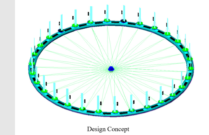
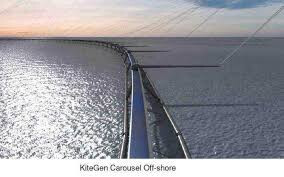
For the offshore version: The ring which supports the aerofoils can be a skeletal structure, made in sections and of neutral buoyancy, mainly several metres below the water line with ” conning towers / floats ” above water and on which the aerofoils are mounted to ensure they are well clear of any storm / freak waves. This achieves 3 things: (1) Boat access to the generating hub. (2) Very little stress on the support structure due to waves as most is below the water. (3) The support structure and the links to the hub create a friction link to the water. The structure and the water become a giant flywheel of millions of tonnes storing multi GWh of energy. As with any battery / flywheel there are losses but Couette flow analysis indicates that this is relatively minimal.

In that manner it is quite easy to ensure that the bottom of any aerofoil is at least 40 metres above the nominal sea level.

Kind Regards

Guy Mercer

Water drag on floating flywheel of a giant VAWT .

PCD of aerofoils = 2500 m
Tip Speed = 25 m/s
overall diameter D= 2600 m Radius R = 1300 m
Displacement depth d = 10 m
Water depth = 62 m Depth under rim H = 62 – 10 = 52 m

Tangential velocity of OD U = 25 x 2600 / 2500 = 26 m/s

Consider spokes creating rotating plane flush with bottom of rim.
Consider cone of tethers creating stationary surface with cone extending to OD.
Consider a stationary wall same distance out as the depth under the rim.

The shear rate Y= U / H =26 / 52 = 0.5 /s
This applies to all rotating surfaces / planes.

Dynamic viscosity of water N = 0.001Ns/m^2

Shearing Stress T = N xY = 0.001 x 0.5 = 0.0005 N/m^2

On the Underside the power required at a radius (r) is T x (2 x Pi x r x dr) x (U x r / R)
which can be integrated between the limits of 0 to R to give T x 2 x Pi x U x R^2 / 3
Underside Power required = 0.0005 x 2 x 3.1416 x 26 x 1300^2 / 3 Nm/s
= 46014 watts

On the OD of Rim power required = T x Pi x D x d x U
= 0.0005 x 3.1416 x 2600 x 10 x 26 Nm/s
= 1062 watts
Total power required = 47076 watts = Less than 50 KW

Let us leave aside the flywheel effect. A perhaps simpler way to save space would be to install a circle of HAWT wind turbines at sea. Part of said wind turbines being in the direction of the wind would operate. Some downwind HAWT could also work if the circle is large enough compared to turbine height. Such an installation would allow to remove the requirement of 5 to 10 times the rotor diameter spacing in all directions between two HAWT.

The first assumption or claim is that there is a need to save space. Can you give some figures to back that up? How much is the lack of space costing the wind industry, or other stake holders? You can then start to compare that cost with the costs of interventions and see if your interventions might make sense.