Crosswind kites are massively studied because they are very efficient in regard to the kite area.
But as any secondary use is at least difficult under a one kilometer tether going fast with high tension and a heavy kite in the end, as a kite-farm of crosswind kites requires spacing of unities in order to avoid mess, tangle and collisions, the power to space use ratio can be very low.
Please @tallakt could you inform us for the size, the power, the tether length of the prototype(s) that Kitemill intended to make fly in this 1.8 km radius and 1 km height zone?
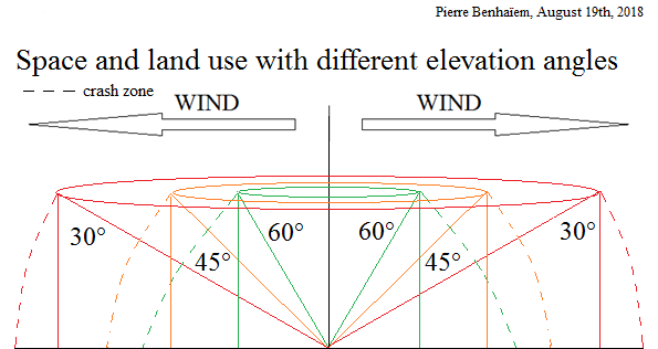
Another sketch to complete:
So some less efficient AWES per kite area can be far more efficient per power/space use ratio which is a far significant information, at least for me.
I cannot comment Kitemill specifics without routing them through the proper channels. I can say that the volume described by Thomas Harklau in his presentation is probably (I have not talked to him about this) made with quite a lot of extra space for future larger models than what we are working on at the moment. Perhaps he intended to put more than one kite in this volume?
The area we use now is not anything like the picture above.
In general terms the issue you are pointing out with land use is real, and I don’t think anyone has really solved this problem yet. The solution so far seems to be:
Going offshore to get more space and, incidentally, more wind
Going to a remote, uninhabited location
I believe also there is a question of perspective here. Most of Norway consists of “unused” space. There are few people in these places. I don’t see a problem finding a site far from humans in Norway. This might be different for people living in more densely populated areas.
The age of co-kites, kites and humans living side by side, is still a bit away for the most prominent rigid wing AWE companies. This could happen in time, if the crash frequency was proven sufficiently low.
Let me also add that most people would be ok with multiple kite rigs in the volume you described above, being staggered mostly parallel in the direction of the wind. The distance between the kites of course depend on tether length, radius, safety concerns and more. But I gather it would be wrong to say that the total “30 degree” land is available for only one unit.
Page 9: “…spacing of around 350 m with a tether length of up 750 m.”
The cylinder of 3.6 km diameter and 1 km height could include about 20 unities. If an unity is 2 MW, the whole is 40 MW. The risks of mess, tangle, and collisions (with 3.5 tons wings) are significant in the case of gusts, several wind directions within the farm, mechanical or computer failure.
In this volume the front air space of 3.6 km² would lead to more than 1 GW with 10 m/s wind speed. Non crosswind AWES including some rotating devices, or lifters carrying turbines, or even some yoyo parachutes, would have a lesser efficiency per kite area, but probably would fill the space with more safety, so more efficiency in the end.
Could be. The difference in view here is the fact that I believe a rigid wing with electric control is easier to operate than a network of passive kites. Time will show who of us, or if any of us, is right. Using rigid wings and electric control simplifies some things and makes other things difficult.
As an example, Peter Lynn spent ages figuring out the single skin pilot kite, and in his email of today, he admitted to having little to show for in terms of progress. Any way you look at it, PL is an experienced kite designer. Doing stuff when limited to simple rules (only one skin in the kite) can make the small things very difficult.
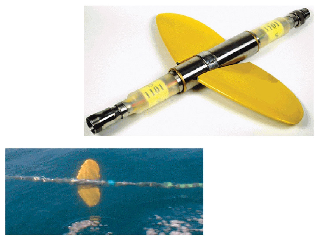
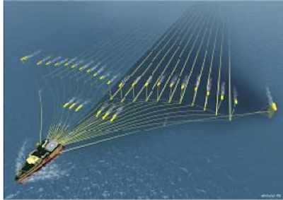
Another view: I previously worked in the seismic industry where we had a vessel towing >300 electrically controlled wing units attached to a cable (streamer). There were 8 of these streamers, with only a few meters distance, and also sometimes in two layers height. The streamers coule be kilometers long. And there would be currents coming from the side, and the vessel would turn 180 degrees now and then. We had some tangles, but mostly it was fine. And the tangles were further between the more mature the system became.
They may look like the 3D renderings of some AWE companies, but these systems were real, and quite successful.
If you are asking about the “Q-Fin” (which it is called, the yellow wing unit), they are placed inline with the streamer. As the streamer has little torsional stiffness it may rotate by a differential wing angle of the two wings, and then by using a common wing angle on both wings, a force may be applied in any direction.
As they are neutrally buyant they don’t really fly like an airplane. Though somewhat similar to a kite, they are also very different. The reason I mentioned them was just to argument that keeping many kites in the air at any one time perhaps is not entirely infeasible. It was difficult in seismic, and would be even more difficult with kites. But not impossible.
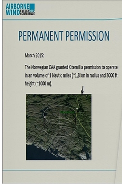
The debate is open. But it is sure that Kitemill took seriously the space use concern with the Pemanent permission for a 3.6 km diameter and 1 km height volume looking like the sketch I made two years before.
Love those wee spinners @tallakt.
The power rating of yo-yo has been a little contentious as it was often quoted in terms of an equivalent standard windmill with capacity factor considered at the same site.
1MW is 1MW dudes
What’s the time it takes for a yo-yo cycle? Why just have 1 kite in that space when you can fit 60 - 100?
As for network rotor turbine arrays. My most successful so far has been a single ring with 3 rigid kite blades. I haven’t had time nor resource yet to stack rigids nor fit them with controls… Both improvements could no doubt make massive gains in performance.
I attach again Kitemill’s Permanent Permission" but alone, with a question.
How much wind power can you extract with the AWES of your choice, and in that volume (taking account of a crash zone), using various arrangements including a kite-farm? Thanks.
Interesting question Pierre,
The very simplest analysis would accept power scales with the frontal area, then if we scale the results of a known system into the 1.8km radius 1km height cylinder calculate the new frontal area and extrapolate old results.
OK this assumes similar properties (solidity, L/D,…) and the physical handling and Lift capability etc etc
However, yeah ok, let’s consider a single daisy space requirement in a cylindrical space and scale.
Wow that’s a big scary Daisy, bagsy I don’t have to handle the launching line…
So lets scale the power 1.4kW peak … lets just say1kW x 10,000 = 10MW
Hefty, but still total pants considering the volume.
Of course if you were going to use the volume more efficiently … layers and multiple Daisys…
A 1.8km radius 1km height cylinder leads to a front airspace of 3.6 km², so a Betz limit (16/27) potential of 1274 MW at 10 m/s wind speed, less losses and unswept area. If reeling yoyo systems are used, the potential becomes 1274/4 = 318 MW, yet a huge value. A fraction of this potential could still be a very high value. Several crosswind AWES with a high efficiency per wing area but requiring high spacing could not fill this space as well as several AWES with lower efficiency per wing area but requiring low spacing.
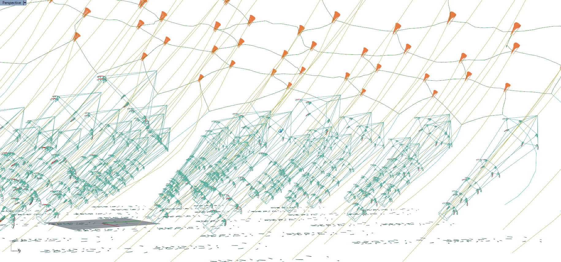
I think the idea of “filling” a volume with kites, to an optimal workable energy extraction density is very interesting.
It’s similar, I think, to what you are looking for in
A large area kite, widely tethered, which handles winds from all directions.
I should probably add a lifting network as pictured above into that topic
Rod, I think a higher value than 10 MW for Daisy would be possible with an appropriate optimization.
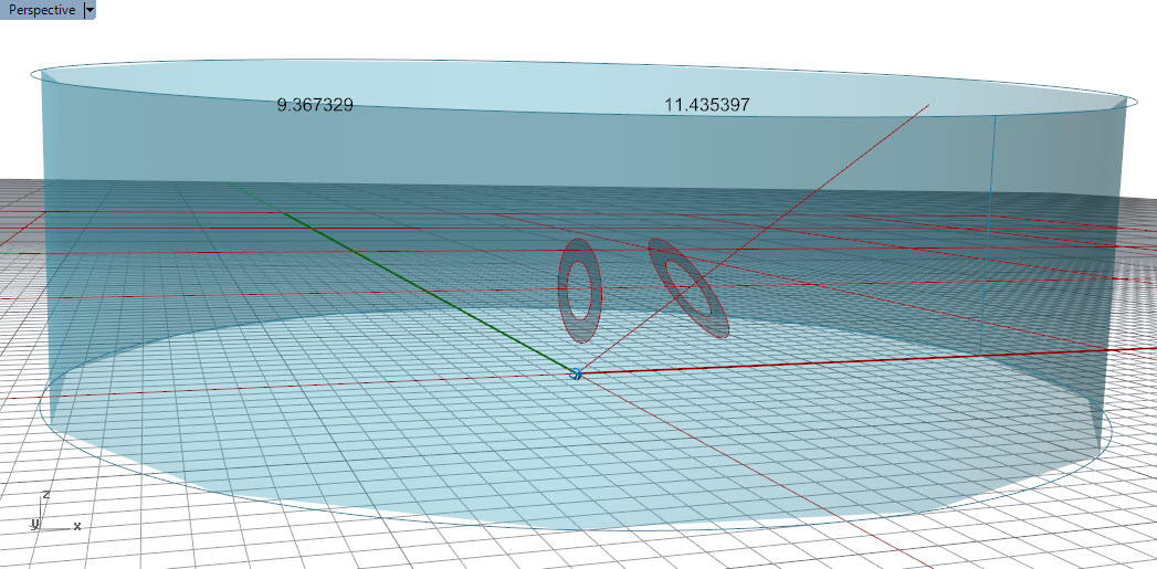
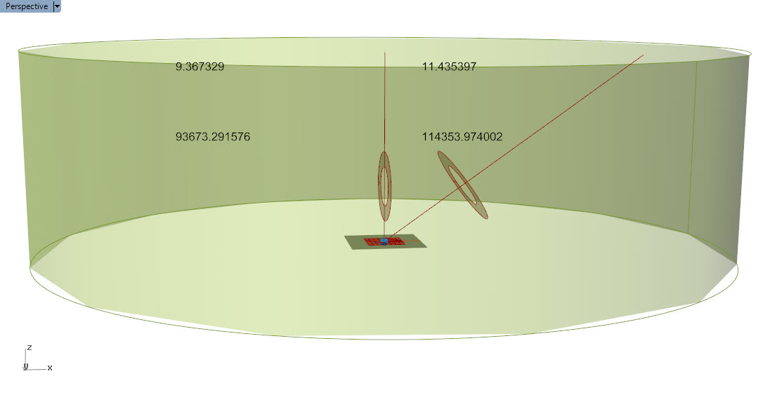
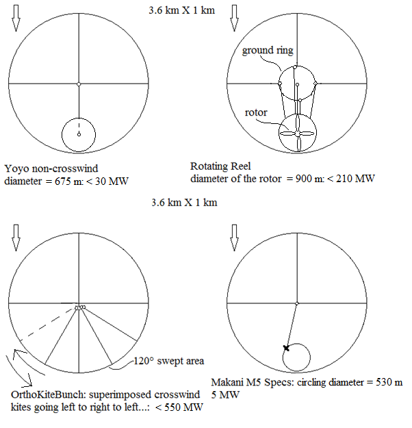
I made a sketch of various AWES within a 3.6 km diameter 1 km height cylindrical volume, in plan views.
One of them is Makani M5 (5 MW) with a circling radius of 265 m as indicated on their FAA document. Two units could be added on both sides of the central unit, for a total of nearly 15 MW. Or other arrangements can be studied. M5 would probably be the most efficient AWES per wing area. But it sweeps far more than the useful Betz limit swept area, adding that the 530 m diameter circle doesn’t optimize the cylindrical volume, and is swept only on its periphery.
Concerning OrthoKiteBunch (see a previous message with the video on Power to space use ratio) the rate is far more higher and can be explained by the geometry of the swept area which is a part of the cylindrical volume periphery, the wings being superimposed in 1 km height, and several bunches of superimposed kites needing to share the 120° of the 180° space. It can be not practically possible.
Concerning rotating reel and a yoyo non-crosswind kite, the diameter is the same but the efficiency of the rotor is theoretically higher because of both stationary swept area and crosswind motion.
Of course when I mention < 30 MW or 210 MW or 550 MW we could divide by 2 or 3 or even more. The size of the wings could be also not reachable.
An observation: 3 wind turbines 1 km height side by side on a pivot could achieve 3/3.6 of 1274 W, so 1061 W.
kPower sees periodic multi-kite airspace as a metamaterial under applicable science predicting lowest density of overall mass is favored. Too much flying mass in a given space fundamentally limits max power; another way of saying that maximum power-to-weight AWES design is favored, including to maximize airspace capacity.
Lets not forget wind velocity as a driving power-to-space and general design factor. Makani’s M5 concept-blunder would make better sense in a constant but unrealistic hurricane-force wind. Its dead at most-probable wind velocities. Beware of these seductive traps of excess-mass design concepts over-promoted by so many ventures, Its time to discern the practical solutions in a race of few winners, many losers.
Largest and lightest power kites in networks working in tight airspaces is kPower’s bet.
"7.1. Effect of flying mass
In all AWESs, increasing the flying mass decreases the tension of the cables. Since Ground-Gen systems rely on cables tension to generate electricity, a higher mass of the aircraft and/or cables decreases the energy production [107] and should not be neglected when modelling [109]. On the contrary, increasing the flying mass in Fly-Gen systems does not affect the energy production even though it still reduces the tension of the cable. Indeed, as a first approximation, the basic equations of Fly-Gen power production do not change if the aircraft/cable mass is included and this is also supported by experimental data[108]. "
Moreover this topic is about power to space use ratio, not about power-to-weight, excepted if there are connections. Could you support “…that maximum power-to-weight AWES design is favored, including to maximize airspace capacity…”? Can be it due to a possible lower path radius? Or safety concerns?
Take a 2mw single-tether kiteplane (like Joby’s model) operating under a 2000ft ceiling. To keep safely clear of neighbors it occupies a circular plot near a mile across. Presume a 3x3 array of nine kiteplanes for 18mw from a 3 mile square kitefarm. The same land developed with conventional 5mw HAWTs, spaced normally, could develop greater than 100mw, presuming that better wind capacity-factor aloft roughly offsets the lowered system availibility of complex delicate aircraft. Conventional HAWTs win overwhelmingly in raw land efficiency without even touching the upper-wind. However, the same land & airspace the nine kiteplanes sparsely occupy can be densely packed with airborne turbines or wingmills, in string latticework based on classic kite methods, for over a rated gigawatt. AWE arrays of cross-linked semi-captive elements seem to have a fantastic advantage in space-efficiency, not just safety & control, over single-tether designs.
I used crude geometric methods to estimate these figures, so it will be fun to see how well someone else’s calculations coincide. A suggestive guesstimate is that there is well over a gigawatt average in a tiny mid-lat crosswind patch of sky, just 100m across & 10km high.“/”