Let us consider a crosswind AWES with an aircraft and a long tether moving fast with high tension, generally at a relatively low elevation angle of about 30-35°.
The footprint can be seen as the area of the ground equipment. AWES footprints can be expected to be low.
In the other hand the land use is the delimited zone by the tether as the radius of said area by taking account of all wind directions. If the tether length is 1 km, the land use would be at least 3.14 km², where secondary use would be difficult or not possible due to heavy and highly tensioned aircraft and long tether going fast. It is the reason why the Power to space use ratio should be considered, not the power/kite area or even the power/footprint ratios, but the power/land use ratio (and also the power/space use ratio delimiting the no flight zone).
Edit: solar power m to km. Added power density of offshore wind farm
Some numbers are necessary. The most important being power density per square km land. Looking at Makani, the M600 claims 600 kW for a 440 m tether. This translates to approx 1.2 MW per km2. If this were part of a farm, the spacing would only be a 440 m grid, as all kites point downwind, placing the number (no edge safety zone though) at 3.0 MW per km2. I would assume tighter spacing should be feasible, and that power density will only increase in the future (eg dual kite systems).
As a comparison, solar farms in europe give you 5 MW per square kilometer (according to above link). But the capacity factor is far poorer compared to AWE.
And stating that the land could not be used is pretty harsh. Why no farming for instance? One could use zero wind days to process the farmlands. Likewise for fisheries offshore.
Additional important note: Tether length should scale with wingspan, so land use should scale with power output (wing area \propto ground area). A small AWE rig should have the same power per km2 as a larger unit, not considering unfortunate scaling of airborne mass…
Also for your worst case calculations (which is fine), the land use would probably be the full extent of the tether as a crashing kite could not be expected to fall straight down, but one could expect the tether not to rupture.
The maximum capacity of a small footprint is as a kite network node. The network itself can be started from an upwind footprint, with a pilot kite enabling connections to other footprints. These starting connections form pilot arches to progressively swap into full-strength AWES structure.
A dense-airspace kite network can be flown from small footprints using ~1/100 land area. In the event of a major emergency, a network could break up and fully retract to its footprints, without impact on other surface activities.
A crosswind arch is a powerful airspace filler. A kite arch from two footprints can be pulled into a straight line to park. Compare with two kites on two footprints that may lay in any direction unless fully retracted. Three small footprints enable iso-orientable tri-tether rigs.
Kite network would be make things still worse: entanglements, mess. In case of major emergency (gusts, whirlpools, opposite winds) the network would unravel for tens of kilometers to sweep everything in its path by ravaging entire regions.
Farms of single or dual-kites are also not realistic. They would lead to a forest of cables in any directions with giant hammers at their ends being capable of massacring an area well beyond the planned ground area, in the case of for computer or tether failure.
For conventional wind turbines we have a tower and a rotor, whatever its size. For an AWES this should be similar: a tether or several tethers (for the tower) and a single proportional flying member (for the rotor), a giant wing making Low radius loop or a rotor such like the infeasible Dr. Beaujean's airborne wind turbine.
Its kPower’s unique claim that single-line kite-farm brush-topologies are most prone to tangle, compared to tight airborne lattices that hold every active kite element in its own cell (kixel).
Pierre has made his prediction that brush topology, with no connections aloft, is not “still worse”. Let testing prove who is right on this vital question of what kitefarm topologies best maximize airspace use, while minimizing footprint area.
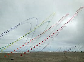
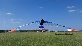
Here is a lot of networked kite to a very small footprint area, with no tangle problem. I have spent years flying and studying these very kite arches with their makers at WSIKF, where Mothra also flew in gale (network of tarp-kites), where Eideken was killed by a giant Osborne parafoil (network of ram-air cells).
No tangles for a well designed kite network. Kite networks develop lattice waves (see videos). A bird is a no-tangle network of feathers whose wing beats are lattice waves.
Spread network anchors offer the densest airspace to footprint area of anything flying. The “staked-out” property is a topological-stability factor.
I am also confident Beaujean’s GW AWES concept is feasible, if not optimal. Hope someone builds one!
Found Glenn’s video. This is the WSIKF event that caused me to move to this legendary location in 2007, to study kites on the beach and at the World Kite Museum. Ohashi himself started the arch-train traditions here-
I think it safe to assume that downwind will be mostly the same direction for two neighboring AWE kites in a farm. Some overlap is possible due to the fact that kites will fly a minimum distance bove ground. Further condensing is possible, though pehaps not initially to be expected, if anticollision or synchronized flight is possible.
I’m not sure where you want to go with this, but: Wind is predominantly always pointing in the same general direction within a smaller open area. Meteorologic anomalies like you describe are site specific or perhaps forecastable, one should not expect normal production in such circumstances.
We might see such an additional safe area for AWE as well. I believe this just relates to the notion that wind energy resouces are not super abundant… this is a good thing for AWE, like Makani said at AWEC, AWE can open untapped offshore wind resources, as an example
At KPS we did demonstrate a stable overlapping system using two soft kites and first generation flight control software, so that to a certain extent showed that it is feasible. We did experience some crossing of tether in some early flights but mostly under manual control, it was not as catastrophic as might be expected and did not result in the loss of the aircraft, in fact provided the kites were de-powered and the tension backed off the situation was always recovered with the kites still airborne: no death spirals. With a powered tethered aircraft featuring a reliable tether release and fly away prevention system most high energy failures can be mitigated.
Brush topology is not good because of possible different winds in the area. Adding network aloft would make the things still worse, by adding constraints linked to supplementary ropes increasing the risks of tangling.
Photos of networked kite are nice, but these kites produce only force, not power. Also some architecture called as network can be in reality a single flying member comprising several elements, not a network as such. For example Beaujean’s AWES could be seen as a network as it contains numerous elements but it is a single flying member. One could make the same remark for an arch like Mothra. Indeed some version of Mothra could deserve to be studied in a powerful (yoyo?) version on a ring allowing facing wind direction, perhaps like on
It has happened before, so it will happen again. The same for computer failures.
Wind changes can occur in a farm area. An example is when the main wind is changing: a kite can be affected before the other kites, leading to increased risks of collisions.
“Perhaps” is not enough. AWES are expected to work 24 h/24 all the year, meeting all possible conditions.
HAWT wind farms are typically arranged in rows normal to the prevailing wind with reduced performance tolerated when wind is parallel to rows. In theory a AWES farm could operate in a similar manner with individual systems spaced to provide optimal overlap normal to wind and left right offsets tolerated when wind is parallel. Of course any such system would have to think with one mind making adjustments for local wind variation throughout flight paths within the array. Certainly a non trivial control problem but likely possible through a machine learning approach.
Spacing unities in a HAWT farm results from efficiency concern.
But spacing unities in an AWES farm should result also and in first from a safety concern.
As the problem of spacing is mainly due to the tether length compared to the size of the wing and the useful swept area, designs with few larger unities could be studied.
It certainly seems logical that larger systems would yield higher power density of array footprint. I think there will be a practical limit to onshore individual AWES size similar to limits in HAWT’s relating to installation logistics, given this assumption holds a offshore AWES array could provide a higher power density.
As for how tangled a network field gets when there is huge turbulence across the field…
I believe this is one of the most compelling reasons to choose network topologies.
Indeed a kite arch can be a possibility to fill the space used, even as I do not see it as a kite network as such. Here the (relatively high) footprint would be the whole ring with the arch, the same as the (low) land use, which is positive. The opposite would be crosswind kite unities (as almost all companies envisage) which have a low footprint but a huge land use compared to a relatively low power.
Indeed this looks like a real network topology, contrary to the arch configuration.
Honestly I don’t see any other possibilities than short term tangles, even with low wind variations, perhaps excepted if the power rotary systems are under…a single lifting arch assuring their spacing.
Untrue. Power is Force over Distance. Even a “static” kite or kite network is a power device, given the distance traveled by wind flow under Galilean Relativity. Mothra can pull a ship or tug against the Earth; its power either way.
A kite network can develop more power than any single kite, as a scaling method. Kite Stacks are a well known kite network variant in power kiting. A kite network can lift WECS units. Its power that lifts mass by kite networks and wind.
Lattice waves in kite networks are visible expressions of Free Energy (Thermodynamics). These waves can be tapped like ocean waves or electrical waves, etc. Waves are powerful.