Ceiling glide ratio vs tether length

I would like to present something I have been working on a little while. Like I mentioned in the other thread (TSR vs glide ratio - #4 by tallakt) I believe maybe HAWT having a TSR of around 9 could be matched by a AWE rig where the overall glide ratio (tether and kite) is above 6. To have a competitive advantage, perhaps aiming for 8:1 overall is a good start, maybe increasing to 10:1 or better later if that was achieved first.

Edit: After @dougselsam 's comment I realized that TSR and glide number should match 1:1.

Note I’m thinking about any AWE rig having single kites flying on single tethers here (eg Kitemill or Ampyx), not other kids of rigs.

So I start with just a tether of diameter 3 mm, then assume it has a zero drag kite attached to it, pulling the ultimate strength of the tether divided by a safety factor 4 at a certain windspeed. Then I assume the kite will fly at a speed being the product of overall glide ratio, wind speed and an elevation angle of 25 degrees.

By using almost no information about the kite, we can see a ceiling glide number achieveable using only tether and a super efficient kite. In short, this ceiling depends on the tensile yield modulus of UHMWPE rope and tether drag coefficient (I use 1.1 here)

I also extend this for kites with a certain L/D ratio.

Anyways; please ask for more questions in the thread if you want. I will attach the source code to produce the plot for any super curious people out there. The result is that you can see from the plot that if you want a certain overall glide ratio, there is a certain maximum possible tether length that could be used, unless you can reduce tether drag somehow. And if the overall glide ratio is high, the tether length is not terribly long.

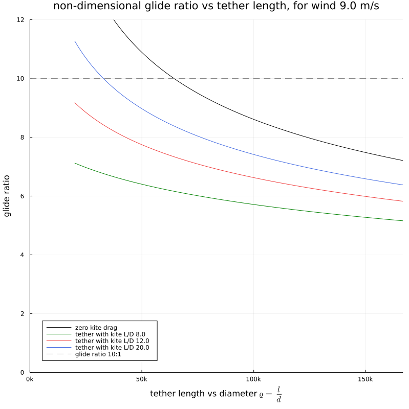
As I made the plot dimensionless, we see eg. for a kite with glide number 20:1 [blue curve] and a goal overall glide ratio of 10:1 [gray dashed line], the value of \varrho should be 35k. To calculate the actual tether length, if the tether diameter is 3 mm, the length is

l = 0.003 \cdot 35.000 = 105 \,\mathrm{m}

If we settle for a glide ratio of 8:1, the tether length of that rig would be \varrho = 75k or 225 m. This would match a kite like Ampyx AP2 with a wingspan of 5-6 m.

Finally, I will again state my feeling that a higher efficiency (overall glide ratio) vs a HAWT TSR is one of the most interesting ways in which an AWE rig can outperform for lower cost.

glide_ratio_ceiling.jl (3.0 KB)

Edit: I updated the plot and numbers as I had by mistake used a drag coefficient too small, not 1.1 for the tether

1 Like

Tallack: To the extent that I can even discern what you are talking about, “elevation angle of 25 degrees”? “TSR is one of the most interesting ways in which an AWE rig can outperform for lower cost.”?
I will just comment about TSR for a regular wind turbine:

  1. The TSR of 6 is chosen to reduce noise and wear. Otherwise it is easy to operate at a higher TSR, by lowering the rotor solidity (2 blades or 3 thinner blades) and flattening the pitch at the tips to zero or near zero
  2. What determines TSR at that point is the drag of the load (generator). An unloaded rotor operates at ridiculously high TSR numbers and often explodes, or has a tower-strike that collapses the whole turbine. An unloaded rotor in light winds just makes a LOT of noise.
  3. I have a friend who made a rotor from modified Samurai sword blades, and ran it unloaded. According to him, it broke the sound barrier, making loud popping noises (sonic booms) and generating a lot of smoke (water vapor from condensation in areas of lowered air pressure.
  4. Kite-reeling is using an unloaded blade to generate drag, perpendicular to its motion, and so is using lift to power a drag machine, so the TSR cannot be compared to a wind turbine.
  5. As you have pointed out, the kite does not operate like a blade because the whole kite is traveling at a mostly similar speed range, whereas a wind turbine blade is slow at the center and fast at the tip. So we’re back to the old “just the tips” meme, which Makani used to love to repeat as a slogan.
  6. In response, I used to have a joke about how people got paid for performing circumcisions “We just work for the tips”… :slight_smile:
1 Like

Many good points here. In particular I missed the TSR of a windmill is loaded, while the glide ratio is for unloaded aircraft. This means that to match the TSR glide ratio should exactly match the glide ratio. And this makes this whole discussion show that AWE probably can’t really benefit much from the proposition of beating HAWT on aerodynamic efficiency.

Wrt point 5 I believe the looping radius for practical purposes must be restrained and that implies that the kite will be working a little bit as a blade. This again implies that the kite must be morphing to some extent if it also must be able to fly nicely in straight paths. With morphing I mean a standard setup with aileron, flaps and rudder may provide enough «morphability».

Thanks for that feedback, really nice food for thought. The question then is really; «Is there a maximum practical flight speed that must be adherred to?» or should AWE try to run at higher speeds regardless

I still think «working for tips» is a good thought. The fast moving tips generate power more efficiently than the root of the blade, with less material spent.

The analysis I provided includes a lot of thought and it’s not easy to convey all that context without resorting to a longer document that nobody will read anyway. Think of the style of AWE Ampyx are doing, and the analysis should match well. If youre doing rotary or multple kites on a single tether, look elsewhere. From that starting point, you could tell me where you are not understanding or in disagreement, and I could take it from there. That being said, I think the end result (the plot) should be intuitively easily interpreted, if you trust me to get the calculations right.

1 Like

@Tallak I reckon this is some of the most insightful and informative work ever done in AWES

1 Like

I have a TRPT version almost ready …

1 Like

Bas Landorp wrote numerous publications about tether drag and glide ratio for a long time.

Long-Term Laddermill Modeling for Site Selection | TU Delft Repositories (PDF available)

See about the figure 15, and also the complete paper:

Fig. 15. Effect of glide ratio on system performance.

  1. Effect of Glide Ratio

The glide ratio of the system is a key parameter governing the cable force. However, Fig. 15 shows
that decreasing the glide ratio by nearly 69% results in a drop in performance of only approximately 3%.To compensate however, much larger kites are needed. The average power per unit cost would be more strongly affected if the kite area is penalized more in the cost function. The required kite area increases by nearly a factor of 5 for a factor of 3 drop in glide ratio.

Hoping this can help to avoid repeating what has already been done.

1 Like

I think if you think this paper describes this figure, I can only describe it as still unstructured thinking. The plot I provided is fundamental to any AWE single kite single tether using UHMWPE tether without fairing or similar tech. It is a very fundamental insight IMHO, only acuired by myself after years of thinking about it.

I am sure others already understood. Just thought i’d share.

Please continue pointing me to interesting papers. Thanks @PierreB

Let me explain an example stumbling block to the thought process; if you want to include kite drag, its very difficult to make the analysis free of wing area, C_L etc. The key insight is that you must assume the wing is dimensioned to pull the maximum allowed pull at a certain wind speed, then the kite falls out of the analysis quite simply. So keeping wind speed as a parameter makes sense, using wing area complicates things

1 Like

As variable the author uses wing area, and you use tether length in place. I think it amounts to the same thing?

No. Because my analysis would cover any kite connected to a UHMWPE tether. Or it could be redone eg. for carbon tube tethers.

You could use the plot to call BS: «Well I dont care what your kite looks like, but the tether you chose cant support a glide number larger than_, and that does not seem to be economically viable when TSR 9 windmills are already mainstream»

For example. But most of all, I found this to be a clear fundamental understanding of the problem, which I did not find in the paper you supplied. On a different note; I dont think the Laddermill fits the description of «Ampyx-like», because the kites travel more along the tether, if I am not misunderstood.

Also, identifying that a glide ratio 8:1 rig requires \varrho of 50k makes you immediately able to gauge a proper tether length for any diameter tether

1 Like

Here Laddermill is used only as an alias. @dougselsam complained about this at length, having designed what was to be called Laddermill, which later became known as a name for a simple yo-yo system after having being the name of the loop device with several wings we know.

And also Bas Landorp was the founder of Ampyx Power.

For the rest it seems that the information overlaps with yours, versus kite against versus tether.

I find the paper is missing many system parameters [glide ratio of the kite, tether length] that I am not able to comment the conclusions.

I just have to state again that I don’t think this paper is very much overlapping with my plot. In that case, you must please state exactly how, or else maybe just leave it there. I feel the paper is mostly about optimizing the cost of the “Laddermill” which is maybe the early Ampyx design.

Edit: my initial response was too harsh, sorry

The early papers on AWES fundamentals by Bas Landorp informed the development AWES has seen. Those papers were amazing.

A breadth of new research, prototyping data, and the concept developments have now come about.

Our new situation has enabled Tallak to develop /discover a new ratio which is hugely informative for AWES design.

Revealing a ratio this fundamental is something we can all celebrate. It probably ought to be named after Tallak

Also, as a result that we here see the maximum tether length, if the production cycle includes reeling out for, say, 72 meters (maybe two loops 2 \cdot 3 \mathrm{m/s} \cdot 12 \mathrm s = 72 \mathrm{m}, that number must be subtracted from the maximum allowed tether length. This means a overall glide ratio for 10:1 is not feasible for that kind of cycle, 8:1 just barely

Or - one may say that drag reducing mechanisms would be required

1 Like

5 posts were merged into an existing topic: Slow Chat

Page 10:

The maximum percentage of cable that can be reeled is 40 %. This combined with ΔL = 200 m
gives a minimum cable length of 500 m.

The Fig. 15 provides the kite area and the cable diameter according to the glide ratio of the full system.

Table 1:
Average Kite CL 0.5

Fig. 12. Histogram of kite lift coefficient.

Fig. 13. Histogram of cable tension.

Table 2 Laddermill Design 2 Based on Site Wind Data
Average Kite CL 1.01

Fig. 20. Histograms of power output and lift coefficient for 10 years of wind data with maximum
reeling speed constrained to be 1/2 of the wind speed.

…

1 Like

I think whether or not this paper is overlapping is less interesting than discussing the subject at hand