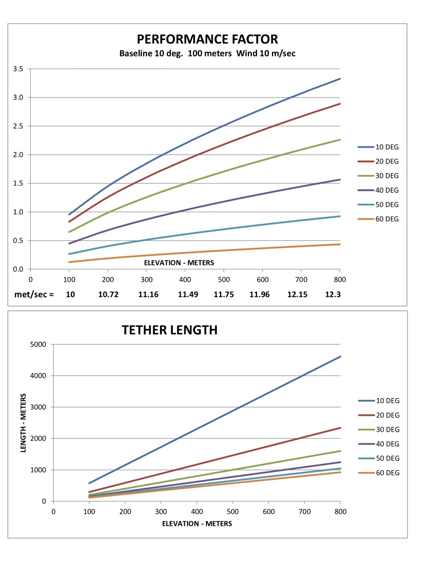
This analysis applies to systems like Daisy, Parotor, MAR3 and even parachute systems where the axis of the turbines or sails are parallel with the tether. With these systems, increase in tether angle results in power losses due to the cosine cubed effect. In contrast, higher altitudes cause an increase in wind velocity with an exponential increase in power. For this analysis I have assumed an aggressive wind profile where wind velocity varies with height by the 0.2 power. Wind velocities are shown on the x-axis of the graph. As expected, the biggest gain in performance factor (power) is achieved at minimum tether angle and maximum altitude. The problem is that tether length is unacceptable at these conditions.
This analysis does not apply to systems with multiple coaxial turbines such as Skyserpent and multiple ring Daisys where masking effects are significant, especially at low tether angles.
The above analysis confirms my opinion that the Kitewinder system is superior to the other systems. The turbine is oriented to face the wind and so there are no cosine cubed losses and the device can operate at much higher altitudes with a relatively short tether (cable drive). The only penalty is the requirement of a larger lifter kite to maintain a higher tether angle. For example, if we assume a tether angle of 45 deg for Kitewinder then the performance factor (power increase) will be 3.48 at 800 meters elevation and the tether length will be 1131 meters. The kiteline angle of the lifter kite must be 60-65 deg. in this case.
The lift is related to the velocity squared, so if your crosswind kite, or blade, sees 7 times the relative wind speed of your lifter kite, your lifter kite would need 49 times the area of your crosswind kite (assuming equal angle of attack and airfoil efficiency) to give the tether going to your crosswind kite an elevation angle of 60/2 = 30 degrees? So that forces you to use an even bigger lifter kite to get higher elevation angles and to counteract the weight of your system?
If my trigonometry is correct, the lift from a lifter kite at an elevation angle of 60 degrees would need to be 2.4 times that of a crosswind kite or blade at an elevation angle of 0 degrees to result in a overall elevation angle of 45 degrees. You would also need to consider the cosine losses of the lifter kite. Is that 50% percent for 60 degrees? So to generate that lift you’d need to double the lifter kite area. If my math is right that changes my 49 times the area of the crosswind kite or blade to 49 * 2.4 * 2 = 235 times. My math might well be wrong.
I asked myself this question for a long time. Perhaps @Ollie could reply.
As when the lifter kite is removed, the rotor goes down to the horizontal at 0° elevation angle, it can be said that it has no positive lift of its own.
On the other hand when held by the lifter kite, the rotor generates lift like an auto-gyro rotor which is tilted by mechanical means.
In this topic @gordon_sp has the blades point directly downwind so the lift from the rotor can be represented as a vector going downwind only.
To represent the vector from the lifter kite you draw a first arrow going up from the origin at an angle of 60 degrees, to represent the lift or drag from the turbine you draw a second arrow that starts from the end of the first arrow and has an angle of 0 degrees. To represent the lift and drag of both combined you draw an arrow going up from the origin at 45 degrees to the end of the second arrow. If you set the length of the second arrow to 1, the length of the y component of the first arrow would be 2.4. This ignores the weight of the system.
If the rotor was aligned with the tether at 45 degrees, the length of the y component of the first arrow would be 0? This again ignores the weight of the system, and probably more things.
The weight of the system would just be a third arrow I think going down from the second arrow. You can adjust the sizes and angles of the 4 arrows to find a configuration you like.
I think this analysis can be as complex as you’d like and still not good enough.
You are on to something but the devil here is in the details; how long tether can you have, how is the rotor oriented, bridling, mass per kite, L/D, everything plays an important part.
In simulations I generally find cosine losses far exceed wing gradient gains. So you end up with the lowest practically useful elevation angle determined by distance to ground and looping radius. Which again may tie in to wingspan and tether length. Tether length again ties in to the L/D of your blades/kites and the solidity of your turbine.
I did make a simulator for this covering «The Pyramid». I dont remember if gradient wind is in there at the moment but I think maybe. The problem in this case is just, «The Pyramid» does not really support very long tethers. Though I’m sure maybe the simulator could be used to produce interesting results for whatever design you are thinking about, if it features rotary power transfer. It would be comparable of course, only a desicated simulation would bring you anywhere close to a precise answer.
Please let me know if you are interested in this, we could run some simulations together.
edit: wind gradient is not there but I am willing to ad it on request. I dont really interest much in wind gradient lately due to the arguments presented above