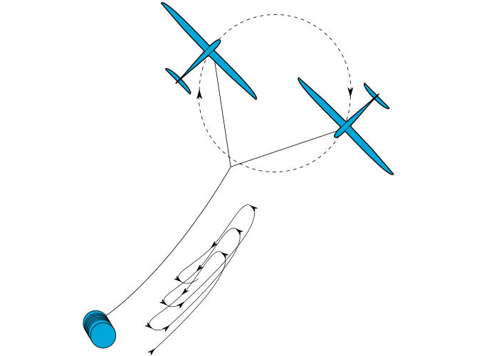
A team of 10 Aerospace Engineering students of TU Delft presented their GreenHyve project during the final symposium of the Design Synthesis Exercise. GreenHyve is about an innovative AWE concept that combines two fast-flying drones with a single tether to access wind energy at higher altitudes. The presentation was video recorded and can be watched here: https://www.youtube.com/watch?v=50irmJ6bVWo
5 Likes
How do the aircraft generate forward velocity in the take off phase? Is there forward propulsion?
Must be. The rotational launch concept had been devised originally by Antonello Cherubini in the frame of his PhD research. See http://www.antonellocherubini.com/dual-drone-project-3d.html. Check out his dissertation for more details.
2 Likes
I would love to hear their take on cubic scaling of tether mass, and the effects this will have for dual drone AWE vs single drone AWE, in utility scale (>3 MW)…
1 Like
Thanks, nice video also but with very optimistically level flight, its seems to me that the tether attachment point would have to translate from the wing tip to the centre as the aircraft climb otherwise they will roll dramatically as soon as tension is applied.
Exciting to see TUDelft students proposing tether hot-swapping (airborne “tether replacement”). This is a basic method for many AWES network topologies, especially to belay between anchor-points, and for megascale rigging assembly aloft. KiteLab Ilwaco pioneered AWES tether hot-swapping starting in 2008, as summarized in [Low-Tech Dynamic Assembly of Airborne Structure, Mar 13, 2011, Old AWES Forum].
I’d recommend contacting them via info@greenhyve.nl
Moving the attachment point when transitioning from lift-off into pulling modes was one of my recommendations to them;-)
The flight dynamics during vertical launch and transition towards the harvesting mode was also addressed in the Q&A. Go to 28:20 min in the video, where the dean of our faculty, Henri Werij, poses this question and the students answer.
Kudos to the students!
Its preferable that TUDelft faculty diligently inform its students of kite network options, including Wubbo’s SpiderMill concept.
I am still waiting for TUDelft response on Kitepower’s tether disposition during the Valkenburg breakaway and crash mishap. Did the tether drag across traffic lanes? Did it snub up just before crash, as the flight data seems to show? The student project retains all the safety vulnerabilities of Kitepower’s architecture, and then some. Identification of weekly tether replacement requirement for reeling AWES stands out as a finding.
I would speculate that having such a long tether requires a highly mass optimized configuration i.e. a low FOS; this may explain its short service life.
Its a bit complex; a longer tether does have a proportionally lower FoS, except when the limiting factor is capstan PTO wear. Then a shorter tether cycled harder has the lower FoS.
Best practice is a heavy-duty tether segment at the capstan, which favors short-stroke pumping. The two kite system considered could do short-stroke modes, even pump each time one of the kites passes the ~7 o’clock position in clockwise rotation, however, there is an effective tether length limit for short-stroke pumping not to be absorbed in line sag.
In a wind velocity gradient with altitude, considerable DS forces accrue, that could enhance short-cycle pumping.
I am referring to FOS on MBL, just one variable in the fibre rope life modelling problem; there is a trade off with mass.
I am not sure what context you are using FOS (you will have to explain), obviously when you model tether life and safety integrity you do have to consider many more things, however in the direct context I was using the FOS on MBL it is not directly connected to tether length or displacement.
Its can be seen from the 7 week life of the top tether section under axial loads only that the MBL FOS is low, as for the 1 week CBOS tether life prediction that could be down to any number of factors.
Simple tether FoS is length sensitive mostly because there is more single-point failure exposure to a longer tether. This is the specific theoretic context. Real safety factors are far more complex.
The simplest FoS maximization heuristic is that many-connected kite network topologies are more robust. A single-line kite fails in dangerous runaway mode with just one line break. Already, a two-line kite with one line break is far more robust; self-kills and retains by the remaining tether. Kite Networks where each element has >2 connections are most inherently reliable against runaway.
Ok, but FoS against what? is this FOS on top of derived tether fatigue life for a specific application/configuration and duty cycle? What dose FOS mean to you?
Safety Factors mostly as used in aeronautics to calculate max g-loads, velocities, etc.
An elevator typically may have an FoS of 8, while an aircraft may operate at 1.5, with far more care and attention required. Industrial riggers also often operate around 1.5, making sure no one is in harm’s way.
Another fundamental metric is MTBF. A system such the students propose will ultimately have to operate >1Mhr without dangerous accidents. Reducing dangerous engineering dependencies is the early path to commercial AWES viability.
Add comm-link and active control dependence to the short list of major AWES risk factors.
Safety Factors are standard engineering.
Here is the closest working similarity case to “Dual-drone AWES” consisting of two COTS TRL9 kites on one tether passively pumping with dynamic stability. Note the heavy tether section at the fairlead. Also study how kPower’s similar starting dual-wing/single-line topology adds symmetry-breaking to function. The upper pilot-lifter kite still dances in mirrored rhythm to its power-kite partner-
It is worth mentioning that the KU Leuven research group led by Moritz Diehl did an incredible amount of work on rotational startup of dual drones under the ERC Highwind umbrella.
Circular runway poster from AWEC2011 reinhartpaelinkawec.pdf (2.7 MB)
And the full research continued in a thesis by M. Clinckemaillie in 2012.
2 Likes
Hi Reinhart,
Billy Roeseler’s visionary ribbon-rotor MSc in the '60s, long before he invented kitesurfing, represents perhaps the earliest reference to this AWES concept space, as he later adapted it for a Boeing internal whitepaper about AWE application.
JoeF may be able to locate the later Boeing AWE concept version.
We also remember Dr. Mark Moore’s work in this concept space at NASA LaRC.
“…the ground tether would connect to the stationary CSR center hub and not experience a [sweep] velocity or drag.”
Like Billy, Mark’s concept variation called for wing surface along the rotating tether sections, with glider-tips unreeling from a complex hub. Billy’s tip aircraft were called “delta pods”: Mark’s tips were more glider-wing like. The challenge of unreeling aloft to full diameter was their trade-off against large circular runways.
One circular runway is surely enough to launch and land large numbers of paired aircraft, much like an airport serves many aircraft. Stacked CSRs are under study, which could rise from one circle.
Two landing and takeoff wheel-trolleys on grass could in principle serve all the rotors.
1 Like
A link:
A quote: “Optimal control is one strategy to prepare for the preliminary design of multi-kite airborne wind energy systems (MAWES).”
And a picture below:
Another link:
My opinion below:
MAWES could be a step towards a maximization of the space when the global swept area will be proportional to the tether length. Besides it a redundancy passive safety could be desirable and included in the “optimal control problem (OCP)” if this is not already achieved. Good continuation!
2 Likes