Energy storage

Hi Doug, it is right. 2x less density than a Tesla battery is ridiculous. That would be true for an object falling from 40 km in continuous acceleration, without any atmosphere.

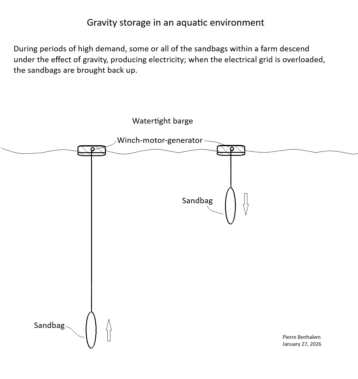
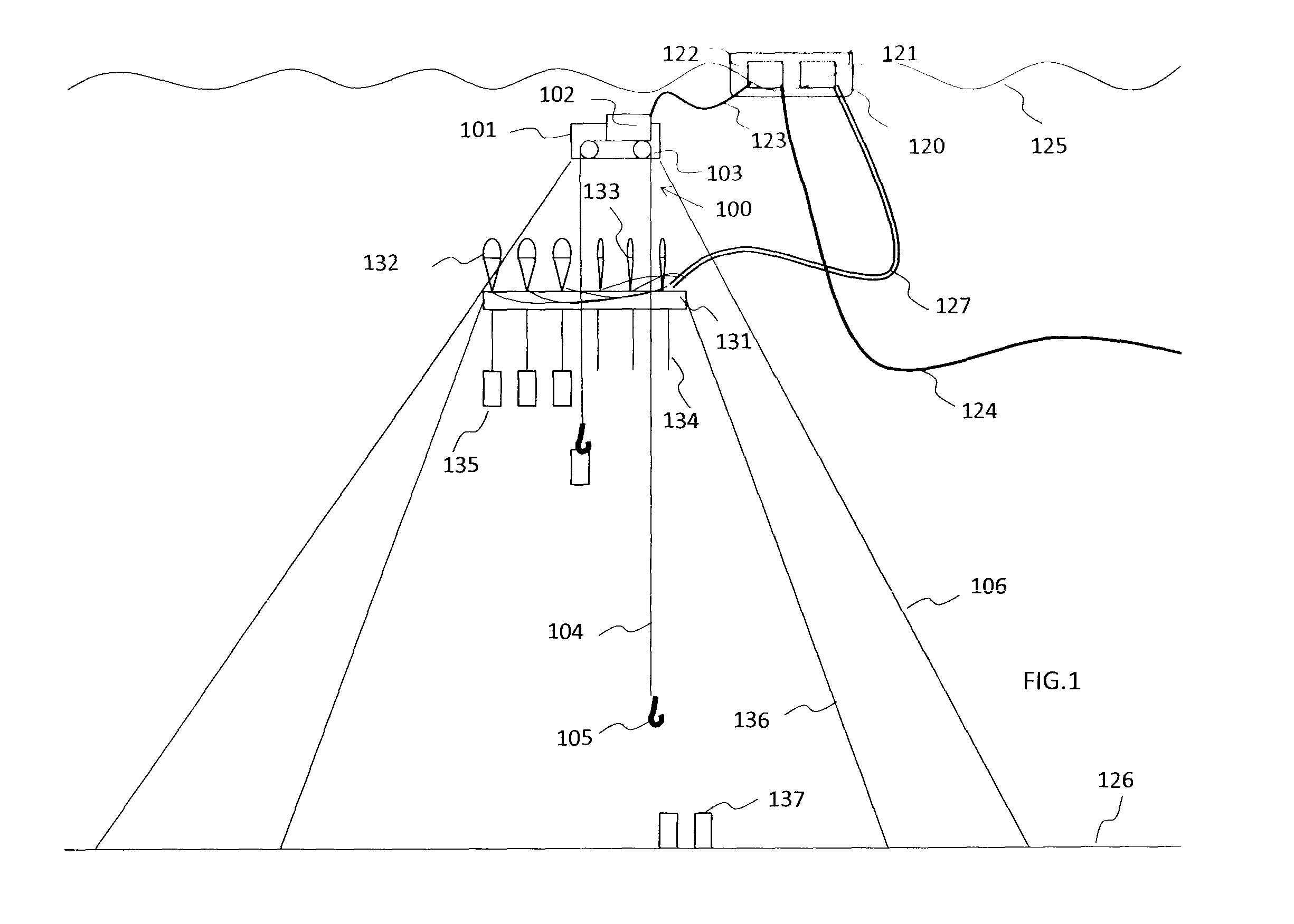
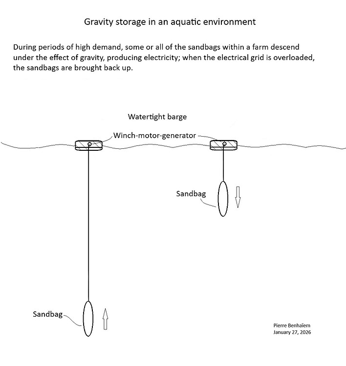
The density of gravity storage is particularly low and relies on the dropping of extremely heavy objects (water and solids), whether for pumped-storage hydroelectric plants (adding the weight of the dams and the concrete lining of the two reservoirs to the water mass), for gravity towers (adding the weight of the structure supporting the concrete blocks), or at sea with barges dropping sandbags. 200x less would still be optimistic.

But this does not mean that gravity storage does not work. After all, pumped-storage hydroelectric plants are efficient and generate few losses, absorbing surpluses from the electrical grid by pumping and then compensating for electricity shortages by generating power.

But since mountains are not everywhere, and we want to develop intermittent renewable energy sources, we are trying to find other solutions like gravity storage towers or their offshore equivalents.

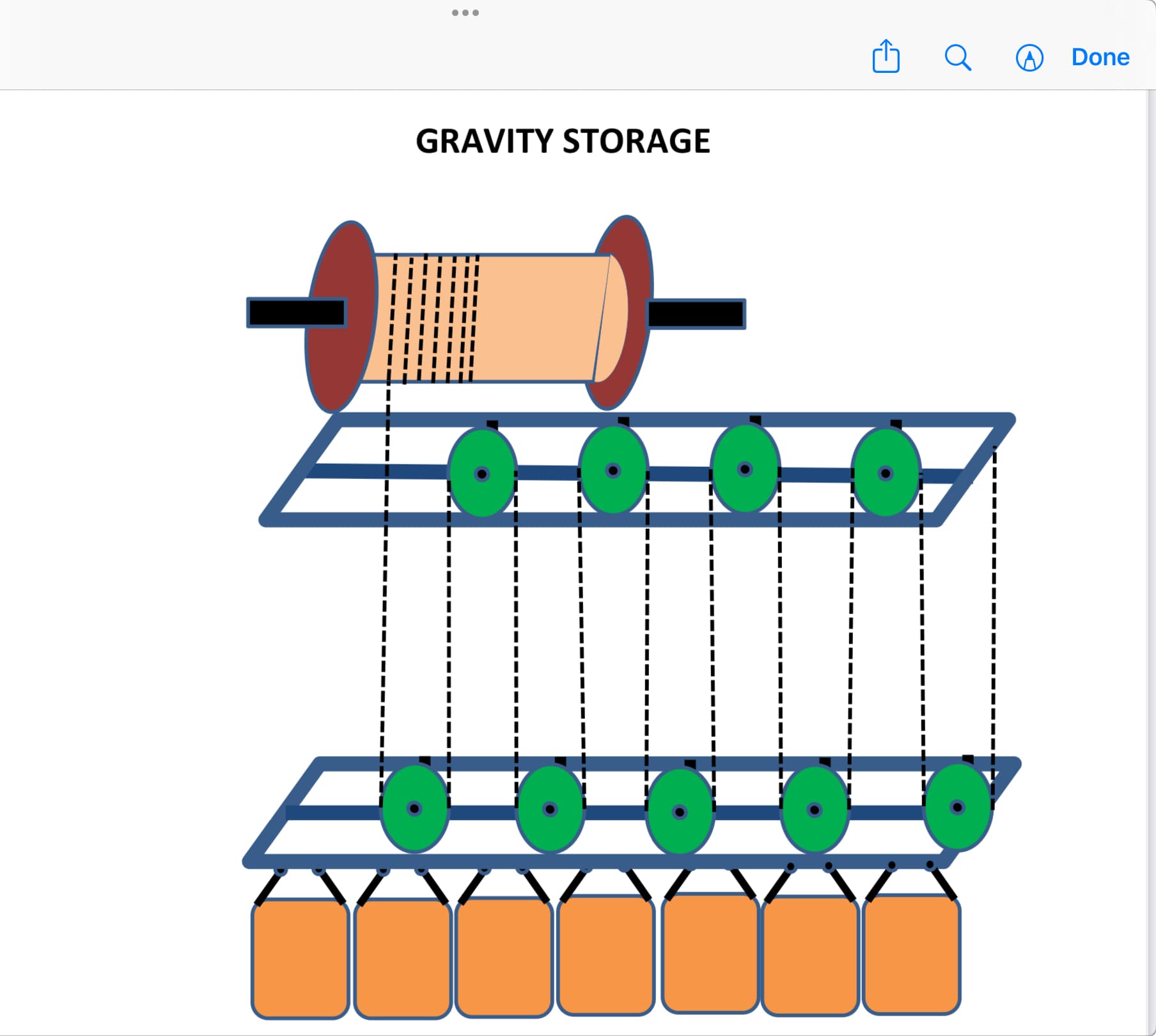
It’s unfortunate that fanciful figures are spoiling the presentation of these concepts, discrediting types of storage that actually make sense. In gravity storage, the heavier it is, the better.

Indeed, as I said above, a ton of sand, which can generate the same amount of energy (over 4000 m and at a stabilized speed of 2 m/s) as a 5 kg Tesla-type battery, will be much less expensive (before the installation of the system of course!) while lasting longer.

About Rudong Tower:

In the picturesque coastal county of Rudong, Jiangsu Province, a 148-meter-tall energy storage tower has emerged, measuring 110 meters in length and 120 meters in width. At 8:18 am on September 26, the main structure of the national demonstration project for gravity energy storage, the Rudong 100MWh Gravity Energy Storage Project, invested and constructed by China Tianying, successfully reached its topping-out milestone, officially commencing the countdown to grid connection.

148 m x 110 m x 120 m = 1,953,600 mÂł, for 100 MWh. Density of concrete can be 2 or a little more. If the tower is 1/10 full of concrete blocks, the mass would be 200,000 tons plus the structure carrying the concrete blocks. The mass of a Tesla battery of 100 MWh (same energy capacity) would be 500 tons, so less than 400x less.

It is already done. About “subtract that result from the original amount of energy”: kinetic energy applies to the moving mass, not to the weight (which is a force), the formula being (in J) 1/2 mv², so there is no subtraction.

Note that water reduces gravity, which means an object falling in water has less acceleration than in air. I had calculated all of this (in air environment instead of water), as well as the kinetic energy of the moving mass, for Solar balloon jumping.

But for gravity storage, water doesn’t change much because we are moving at fairly low, stabilized speeds (leading to minimizing density energy), and therefore with reduced hydro drag losses. The key is not to waste too much energy going back and forth.

If there is 584/1000 * 1000 * 9.81 * 4000 = 22916160 Joules of potential energy available from an object, and it falls during 1800 seconds, that gives you an average of 12731.2 Watts over those 1800 seconds. You would subtract from that losses like friction.

The eventual speed of the falling weight is after most of it is used to power the generator, so you can’t use that, other than perhaps in calculating how much hydrodynamic losses it still experiences at those speeds.

1 Like

That is a relevant statement.
584/1000 could correspond to 5.729 (gravity of concrete in water) / 9.81 (earth gravity) I used. The result is the same:

GPE Formula = mgh: m for mass, g for acceleration due to gravity, h for height.

The use of the formula (for 1000 kg without atmosphere, without limit speed):

But I did not use this formula [I should have used it and adapted it due to buoyancy in water like above, though] (I suggested it by mentionning “stabilized speed”) to comment said first video, since the speed of fall (here in water) is stabilized at 2.22 m/s, during the time of fall from 4000 m (1800 seconds). There is no acceleration during falling after the stabilized speed of 2.22 m/s. The stabilized speed is reached by the wanted torque of the winch-generator (and not due to the limit velocity due to hydro drag), and is reached in less than a second, even with gravity reduced by water due to buoyancy. In this example, the potential energy is far to be fully used.

I should correct the passage that you quoted (below) as well as the previous passage because the potential energy is used:

There are losses of course, like for pumped-storage plants.

Seems to me that we should recognize pumped water storage as viable, since it is known to work well, and most of the rest are just ignorant hypothesizing by clueless crackpots. If someone has a good way to do gravity energy storage, just build one and show the world how damn smart you are! The concepts are dirt-simple, so is everyone dirt-stupid? Build one! At any scale! In your backyard! Once again, facts versus endless handwaving-and-happy-talk idiocy.

1 Like

The potential energy is being converted into electricity. That’s why you see the slower speed: https://youtu.be/uqmT1GzRXWI?t=394 In that example you can’t say the pendulum is not moving at the end so there is no electricity that can be harvested; it was already harvested.

1 Like

This could look like an hydro storage version of Gravitricity as shown below (see the video).

Gravitricity

Pdf available on the link below.

And also:

For a given height, a mass would deliver the same kWh regardless of the speed, and therefore the duration, of the descent (assuming that hydrodynamic losses are not taken into account and that there is no speed limit). Is that correct?

I will then correct my calculation based on a stabilized speed, adopting @Windy_Skies’ calculation. That would increase the energy density of gravity storage, compared to the values I provided.

  1. This “all-ya-gotta-do-is” supposed “solution” to wind intermittency is irrelevant to AWE if there is no working AWE system to “rescue” from itself…

  2. The simple reason pumped hydro works, while solid weights do not pencil out, is that liquids flow easily through turbines (back to turbines again, eh?) rather than requiring multiple goofy cranes connecting and disconnecting from blocks all day - which is completely stupid “Rube Goldberg” sheet if you ask me…

  3. The reason I say if you believe in this crap, build one in your backyard is you can power your home for hours using just $500 worth of LFP batteries that take up just a few cubic feet and fit into a very small space. Think of how high a structure and how much weight you would need to match the LFP batteries and then maybe wake up from your neverending hallucinations! :slight_smile:

“Rube Rudberg”, "La Brea Tar Pits, “Crackpot”, “stupid”, “idiot” etc. : always the same rant. No need to argue anything.

Assuming height is 4000 m, the stabilized falling speed is 2 m/s, the fall time being 2000 seconds.
First, I will present the equation in the correct form proposed by @Windy_Skies here, then correct the result in the end:
120,000/320,000 x 320,000 x 9.81 x 4000 = 4,708,800,000 Joules, or 1308 kWh, leading to an average of 2,354,400 W (2.3544 MW) during the fall time (2000 seconds).

For 1 ton, it would be:
375/1000 x 1000 x 9.81 x 4000 = 14,715,000 Joules, or 4.0875 kWh, leading to an average of 7357.5 W (7.3575 kW) during the fall time (2000 seconds).

Subtract the various losses.

Concrete production emits a significant amount of CO2, primarily due to cement, which, along with sand, is one of its constituents. Projects [6, 7, 8 and 9], requiring high precision, necessitate the use of concrete blocks. In contrast, sand, which is even far less expensive than already inexpensive concrete, does not require such precision and is therefore well-suited to the project presented, especially since it does not present the CO2 emission problems associated with concrete production.

There are no mechanical parts underwater: only the sandbag and its rope, which is connected to the winch-motor-generator on the barge. The barges are watertight and equipped with a hatch protecting the winch-motor-generators which are placed low to lower the center of gravity.

Anchoring to the seabed would be comparable to that of an offshore oil rig, once the barges are connected by short ropes. The sandbags permanently placed under each barge also help lower their center of gravity and stabilize them, much like the ballast used for ships.

(PDF) Gravity storage in an aquatic environment. Available from: https://www.researchgate.net/publication/400054770_Gravity_storage_in_an_aquatic_environment [accessed Jan 31 2026].

Wet sand is 2x the density of water

Useless comment. It’s already stated in the document. DOI: 10.13140/RG.2.2.33141.44006

Hi Pierre: Thanks for listing my accurate diagnoses of what is commonly declared and promised, versus reality. How many AWE promises have turned out to be true thusfar?

How many energy storage “breakthroughs” do you read about every single day? ten? How many times is it true? Zero?

How many wind energy “breakthroughs” have we examined here? hundreds? 1000? How many have turned out to be true?

How many AWE “solutions” have been promised? How many have come true?

The conversations here would not take place in a forum of people experienced in wind energy. Instead, all that is said here would be happily and accurately debunked. As it is I remain the lone voice in AWE with knowledge of wind energy.

When we talk of “intelligence” we refer to the accuracy of a mental image of reality. A mental model that reflects reality is referred to as “smart”. A mental model that does not reflect reality is called “stupid”.

If a supposed innovator’s pronouncements, handwaving and happy-talk reflect only fantasy, and the promises made are revealed as false, reflecting a misunderstanding of the basic subject matter, that supposed innovator is referred to as “a crackpot”.

While its very entertaining to roll around in the endless fantasies of crackpots, its also a good idea to recognize the ignorant fantasies as what they are: Beginners unwilling to get up to speed on the subject matter, nevertheless posing as innovators.

At some point, either you can see reality and deal with it, or live in a self-imposed fantasy-world. :slight_smile:

Gravitricity company would use abandoned mine shafts. In this video, the two concepts from Energy Vault are compared with Gravitricity’s concept.

I like the term “Dam(n) Smart”
why not recognise a tidal flow (Like an east west aligned fjord kinda thing)
At the West end string across a deploy-able dam
a tight rope top layer with large inflatable floats lifting up a sheet (the dam wall) a tensile dam wall. The bottom edge of the sheet being held across the fjord and up the walls by heavy material ~rock filled gabians

Opperation
1 drop the sheet to let the tide into the fjord
2 inflate the topside boom to lift the sheet wall
3 let the tide out through a turbine and maybe some vents
4 repeat

ok it’s not a storage idea sorry
and it reeks of “all you gotta do is…”

The patent for this technology:

WO2017067987 ELETRIC ENERGY GENERATION AND STORAGE SYSTEM FOR AQUATIC AND SUBAQUATIC ENVIRONMENT

Electric energy generation and storage system for an aquatic environment, comprising: - a plurality of weights (135), attached to an underwater platform PAP (131) positioned at a sufficient depth to avoid surface currents and the effects of bad weather - an ascender - generator (100), arranged in conjunction with the weights (135) and positioned in such a way as to allow, in generator mode, the said weights to descend toward the bottom zone (126) and, in motor mode, the said weights to rise back towards the surface (125); - a main underwater platform positioned at a sufficient depth to avoid surface currents and the effects of bad weather (101), able to support beneath the surface the upper portion of the ascender - generator (100); - a reversible motor (102) collaborating with the ascender - generator (100) and in generator mode allowing the production of electrical energy thanks to the action of the weights (135) as they descend and, in motor mode, allowing actuation of the ascender - generator (100) so as to cause the weights (135) to rise back up.

My take: attaching and detaching the weights, using hooks acted by an underwater robot, adds enormous and, in my opinion, unnecessary complexity, unless I have missed something. Why not simply attach each weight to the respective winch of the barge (or float), as shown in my sketch, ascending and descending without detaching and attaching?

The anchoring system has not yet been drawn on my sketch, but it could be equivalent to the anchoring shown in the patent above, perhaps an oil platform type anchor. For such a system, one must consider not only surface winds and currents, but also deep-sea currents (in addition to tides) which can be violent and destabilize the weights (wet sandbags) and structure.

I think that the setup, by detaching and reattaching many weights, allows the use of a single motor-elevator-generator, and not a very large one.

But, in my opinion, these weights are still quite small considering the needs of large-scale storage. Perhaps it would be better to use fewer, much heavier masses that are still fixed to avoid the perilous and complex, and probably costly, operations of hooking and unhooking.

The winch-motor-generator could be a hoist-motor-generator.

See a giant hoist (capacity 10,000 T):

The Crane Ship That Lifted a 15-Story Building

Another thing: on the patent, couldn’t the floating platform (120) with electrical equipment be removed, since this equipment goes into the submerged platform (101)?

I agree with you, Pierre, that most of the gravity storage systems devised are much too complicated and the ideal system is one with a single winch and a single weight or group of weights, which is driven by a single cable. also believe that it is less expensive to dig a hole rather than construct a building.
One of the most expensive parts of the system, and probably a great source of inefficiency is the gear reducer since the cable travels at a very slow rate. It occurs to me that if we vary the speed of the rope by means of a system of pulleys, we can improve the gear ratio. In the attached drawing each set of two pulleys increases the rope speed by a factor of 2 and also decreases the tension in the rope in the same ratio. Therefore, a much lighter rope can be used. There is a possible problem that the whole device might tilt as it is raised or lowered. To prevent this we could have two pulley systems back-to-back on a common base.

1 Like

Trying to estimate energy storage costs for dyneema rope:

Found a quote for 16mm rope, 1000m long: 17800 EUR, breaking strength: 192kN

Max energy: 192000 * 1000 = 192Mjoule = 53.3333 kwh

Storage price 333.75 EUR per kwh - more expensive than current battery technology.

In practice would need at least 3:1 safety factor which would rise the kwh price to 1000EUR/kwh

That’s price for rope alone, cost for sinkers (concrete blocks), rafters, gears, motors would add to these and assuming 100% efficiency.

It explains why they considered a lifter/sinker robot servicing multiple rafter-sinker pairs : to save on rope and gears. It also allows capacity increase without investing in lifting/power capacity.

Edit: Just for comparison, poured concrete price would be 2000EUR for a 20ton sinker, probably double if one considers steel reinforcement and that 60% more is needed to compensate for water density

Edit 2: Maitenance costs, which are expected to be high in marine environment, are also significantly minimised, by having all massive structures - sinkers and rafts - entirely passive (no moving parts) while the robot is comparatively small, which makes it much cheaper to handle both maintenance and failures - have a spare robot available to replace a broken one, tow the robot to a shipping yard for maintenance and/or repairs.