From this is it possible to deduce how it scales up? As a mast of boat?
First things first, what is that, exactly?
See the comments below this video for some issues with the “Superturbine”:
")
There’s a bending force on masts, torsional load on the sky serpent shaft.
1 Like
On the video there are several devices:
-
Multi-rotor wind turbine with generator as counterweight: Espacenet - Document original
A multiplicity of rotors attached to a common shaft and settled on a pivot on a supporting tower. -
Stationary co-axial multi-rotor wind turbine supported by continuous central driveshaft: Espacenet - Document original. The shaft is held by the two ends.
-
Serpentine wind turbine (sky serpent, 10’30" after video start, with balloon): Espacenet - Document original
The shaft is held by one end, the other end being held by a kite or balloons.
This topic is about the third device: sky serpent, called also Serpentine.
A mast of boat is held by one end, just like Serpentine. But the bending force is perpendicular to the mast. Concerning Serpentine the forces should be more detailed in order to deduce how the shaft could scale up.
So funny, at about 2 minutes: “there are no million-dollar science labs here”
Meanwhile, across the railroad tracks, is the multi-million-dollar Air Force Rocket Propulsion Lab… 
People think there is nobody and nothing in the desert, but there is!
People out there have airports in their backyards and even kids fly, with no license.
1 Like
Could you @dougselsam state some calculations about the shaft? Ie: weight per length and how much torque before they break?
Let me start by a simple analysis. The numbers are chosen q bit arbitrarily, so they are probably not close to anything usable, but the point is to examine scaling effects here.
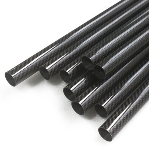
I’ll start by considering an ebay carbon tube which is outer diameter 32 mm and inner diameter 30 mm. The weave is one along the tube (#1) and one normal to the tube along the circumference of the circle (#2).
(I’m sorry if these calculations are completely off, I don’t actually know these things)
Avg radius is 0.031 m, thickness 2 mm. The amount of carbon (#2) is assumed to be half for simplicity.
Inner and outer radius:
r_i = 0.015
r_o = 0.016
The density of this shaft is ~1.5 g/cm^3 which calculates to 0.14 kg per meter of tubing.
Ultimate tensile strength of carbon epoxy:
tau_yield = 1.6e9 N/m^2
T_max = (tau_yield / 2) * J_zz / r ~ (tau_yield / 2) * pi/2(r_o^4 - r_i^4) / r_o
If we state that we want to scale the shaft linearly, we could define r_i to be:
r_i = K * r_o, K = 30/32
This gives
T_max = (tau_yield / 2) * pi / 2 * r_o^3 (1-K)
For this particular shaft, maximum torque should be:
T_max = 322 Nm
Next we’ll assume that the shaft is carrying wings of diameter 2 meter. At optimum efficiency I would expect the wings to be moving at eg. 5 times wind speed. And lets assume wind speed is 10 m/s.
P_max = (50 * 322) W ~ 16 kW
Which is not bad IMHO.
Now Lets scale 10x.
Wings are now 20 m diameter. This reduces the rotational speed by a factor of 10 since the wingtips still need to move the same speed.
Scaling the tube increases the weight by a factor of 1000 (cube law) and T_max by a factor of 1000 also (due to r_o^3 factor). The weight to torque seems to be constant, which is a good thing. Note that I am also scaling shaft length by 10x, which is a bit questionable.
Because the swept area of the wings are now increased by a factor of 100, and rotational speed reduced by a factor 10, the torque should be increased 1000x to maintain the same balance of power output vs material use for the rig. This corresponds exactly with scaling the diameter of the shaft linearly with scale otherwise.
The power of the 10x rig is therefore:
P_10x_max = (5 * 322.000)W = 1.6 MW
Generally I can conclude from this (very leaky) analysis that for a scaling factor S, power increases with the formula
P_S_max = P_max * S^2
Looking at the mass to pull ratio, things look a little less optimistic. Pull increases with swept area S^2. The mass of the shaft, given that the scaling is as above, scales with S^3.
At some point it would be reasonable to think that a maximum feasible scale of the Sky Serpent had been reached. The dimension might probably be extended by adding pilot lifters along the shaft.
So, all in all, I give the Sky Serpent the thumbs up, with the note that once a smaller design has been evaluated wrt power vs weight, the maximum scaling could be calculated taking into account the cubic weight scaling of the shaft.
Another observation: Small wings rotate with a higher rotational speed. This allow higher power transfer through the same shaft. Many small wings seem a lot better than fewer large diameter ones in this respect.
One final note: We could increase the diameter of the shaft and fill the core with foam to support the compressive forces. An increase of scale factor T in this respect, scaling the diameter but keeping the same amount of carbon, will increase the torque by:
T_max * T < T_T_max < T_max * T^3
I am not sure exactly what the scaling would be here, probably closer to T_max * T^2.5 than T_max * T^1.5. This means that scaling the tether diameter making the shell relatively thinner is very effective. But it could probably only be done to a certain extent, as scaling indefinitely would lead to a very lightweight foam core in a super thin carbon wrapping, a design that would break in practical use. Still, a factor 10x in torque over the ebay carbon tubes should not be a big problem to achieve.
2 Likes
That’s some quality content, @tallakt. (Haven’t made the effort to be able to confirm results though)
Another aspect to consider is the roation when bent. I don’t see any universal (or constant velocity) joints within the shaft of the superturbine. That means that there is a cycle of expansion and contraction for every rotation. Would be interesting to see what the relationship between distance between the bearings, length of the shaft, diameter of the shaft and the expansion/contraction distance. Probably easy to make some geometric calculations, but very difficult to get something that correctly models real world mechanics. The problem is basic enough, that someone porbably has worked it out. The obvious relations are: The straighter the shaft (distance bearing = lengthe shaft) and the smaller the diameter of the shaft, the better.
I am not sure it this is a problem (expansion an contraction) as carbon if bent only slightly will act as a spring. I have no idea when fatigue occurs, but in worst case the shaft would have to be replaced periodically.
A way to control lift could be to angle the wings other than 90 deg to the shaft, and then make the wing change angle of attack during rotation.
Details: Lets say the wings face slightly towards ground anchor. Due to geometry, the wing will pull more on the lower wing compared to the upper wing. This generates pull towards the ground and is opposite if what we want.
To change this effect, use a wing profile with negative moment (auto stable like a flying wing) for one part of the wing and attach the angle of attack rotation to a spring. This will make the wing depower itself.
Now the trick: the rest of the wing has almost zero wing moment. So when the first part of the wing depowers, the second part depowers even more. What we want is to get less power the more wind that hits the blades. If this can be accomplished, the wing pointing upwards will contribute to lifting the shaft.
Quite difficult indeed.
Of course you would need a secondary controller to adjust the power to the wind speed. In general less power for more wind is not a good thing.
1 Like
That’s incuring a compexity penalty.
I don’t yet understand how this would work.
Would it be possible to steer the system so that the shaft is at an angle to the wind direction? Because that could be acchieved relatively easily with a lifter system.
Probably a crackpot idea but throwing it out there anyway: One could have the propellar at an angle to the shaft. This could be acchieved by something like a CV Joint. In contrast to the gif, the green axle would continue and the red part would be like the middle section of a sphere with the propellers attached. Now what is needed is something to keep the propeller at the desired angle. That could be a ring bearing on the propeller hub which connects to something that can be kept stable. Simplest solution would be a weight, but more weight is obviously bad. Maybe an rod running below the rest of the system. Maybe weights.
This mechanism could also be used to put the propellers at an angle sideways to get more swept area, in the ‘tensioned between mountains’ use case. The added complexiy probably makes it not worth it though.
I madea a drawing: superturbine variant
And implementing rotors for torque and power generation, alternating with autogyro-like rotors for lift?
If the autogyros are just for lift one might as well use lifters.
Autogyros can produce also a little torque. But it can be better to segment the axis to reach higher altitude winds, using torque rotors on the same shaft, then autogyros and a kite lifter on a rope or a stick, then another shaft with torque rotors and generator aloft, then autogyros and a kite on a rope, and so on, finally maybe.
But how would one make use from the torque of the autogyros? They can’t be on the same shaft as the regular propellers. This sounds overly complicated. The gyrokite by sky windpower would be a simpler, better, solution than that.
The small torque of the autogyros would be used like the large torque of the other propellers, all the propellers being on the same shaft, but above all autogyros would bring thrust and lift.
OR
The torque of the autogyros is not used as only thrust and lift are used like on http://cdn.pes.eu.com/assets/misc_new/peswindissue17talkingpointskylimitpdf-891355291894.pdf for only one autogyro. The shaft can be segmented.
Yes both are complicated.
The Sky windpower autogyro-helicopter uses torque with a generator aloft. It is simpler but the swept area is limited in regard to the tether length.
Individual sections not too long, larger diameter, and pressurized (of filled with foam):
I think, like I said earlier, that that does not hold for thin-walled structures.
For a thin-walled structure, most of the extra volume is air, which is of course neutrally buoyant in air.
Related, from the YouTube comments under the video I linked earlier in this thread:
I took that into account. When scaling linearily, the torque capacity increases more than linearily. Still all in all its not all rosy and not impossible
2 Likes
As blade material scaling is also discussed, here is a link of a manufacturer of blades for wind turbines:
http://atv.tm.free.fr/EN_blades.htm.
ATV 03m00 http://atv.tm.free.fr/FT_ATV_03m00.pdf compared to ATV 28m30 http://atv.tm.free.fr/FT_ATV_28m30.pdf seems indicate that the mass of these blades scales lower than a cubed rate.
2 Likes
Searching for “turbine blade size logarithmic” gives this for example, which I think might also be relevant for a drive shaft:
Upscaling_Wind_Turbines.pdf (1.1 MB)
See: 2. THEORETICAL UPSCALING
3 Likes
IMHO a blade could scale like a drive shaft for its hollow part towards the root.