KGM1 has now validated its own technology, with a graph where the Power/time is ALWAYS above “0” and never “negative”.
In April, another flight test on the machine, again in light and variable wind conditions, but performed with three different pilots (the machine is easy to fly, also without any assistance). Just only this could represent a +30% respect benchmarking.
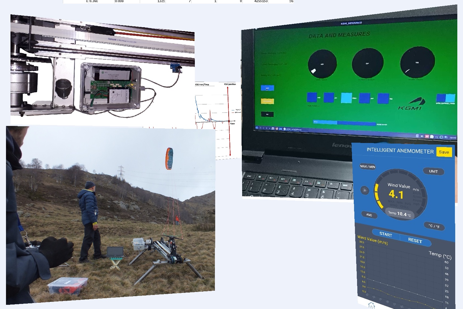
The GUI data log gives us new evidence of the unprecedented duty cycle, made possible thanks to the elastic elements and kinetic accumulators, making the KGM1 the first AWE generator in the world that has demonstrated completely free operation of a feedback motor, which - hoping - will open new research fronts in the AWE sector.
Here is the link to the video (test 2022-04-23): Filmato TEST 2023-04-15 - YouTube
There is still a lot of work before arriving at a mass-produced product - the next prototype will have to hunt for “kW” (now that the technology is validated) - but I continue to “see” unexplored potential and many variables to work on.
And a scalability, introducing some completions on larger machines, while maintaining compact sizes.
But I think this is the maximum possible development working in my home cellar, with “0” money, in the free-time, alone and thanks to some friends, son, wife and a “non-formalized team”.
.
Any suggestion for help this challange is well accepted!
4 Likes
This is a very impressive achievement. And very cool
Exceptional work! The reciprocating “rowing machine” method is brilliant, typically with cross wind power it is common to reel out line and generate power off the spool, with your system the line is static and seems to have quick power cycles, I have seen this before, but your approach is very well thought out, even down to the angle of the kite bar. I have seen models (only sketches) of this design on a super long track or circuit, and the kites can then “reset” the power cycle under their own power.
Just curious, what do you think about the power output of a kite loop vs a figure 8? I think loops would make the perfect reciprocating motion for the energy capture system
1 Like
Thanks for your feedback!
Thanks for your feedback Christian.
Regarding the kite loop vs a figure 8 I suppose there is not enough depowering: consider that KGM1 has a “dynamic depower” on board the same duty cycle, and the kite itself (like the generator) never stops its flight, conserving its kinetic energy, but it does so by getting out of the “power zone”.
In this way the elastic elements are able to automatically manage the passive phases (working on short time transients), while the generator continues to work. It work exatly like a motor.
I don’t know if this is a different question, but why not put your “bench” perpendicular to the wind instead of in line with it? Now you have to tune your system (elastic bands) every time the wind speed changes it seems to let them pull with enough force to move the carriage back when the kite moves out of the wind window and with that, if you want to keep the system simple, a very short power stroke.
If you put the bench perpendicular to the wind, you can do away with the elastic and just let the resistance of the generator vary with how much the kite is pulling. You can also then more easily make the bench longer as then the ending position of one cycle is the starting position of the next, instead of having to use the elastic to move the carriage back.
Control could then also perhaps become easier as you could detect when the carriage reaches the end of the bench and let that tell the control system to start a turn? And you could then also measure the wind speed and carriage speed and keep that at a ratio you like by varying the generator resistance?
I guess an easy upgrade could be to replace this with an electrical motor/generator.
1 Like
what about power output produced during test ? do you have recorded data ?
It’s certainly possible, but for now it’s not my intention to “travel upwind”, but to extract the maximum energy from the wind; in any case it does not necessarily have to be 100% aligned with the generator.
The next prototype will have a differential tensioning system, and generator braking torque management, to compensate for variable weather conditions.
While the ultimate goal of this prototype was precisely to validate the operation, while the next one will “hunt for kW”.
1 Like
Hello, the ultimate goal of this prototype was precisely to validate the operation, while the next one will “hunt for kW”. With - hoping - a budget not “0” and not only using our free time.
1 Like
Something similar…maybe. But I fully confirme your observation!
1 Like
Is there a way to seek funding for this project? Any specific EU channels? This concept has proven to work, perhaps on a proof of concept scale, but one would think there would be interest in something that can actually work? Sorry if I sound naive.
MarcoGhiva, Though this is a prototype, what do you think the cost of an individual unit would be? Is this to be scaled for kW?
Hi Christian,
thanks for any your comment.
I’m a really bad in searching funding, but now we are signed a business development agreement, and another is work in progress.
With the last flight tests we have reach the maximum development, possible without any budget and using only the out of work time.
Concerning costs and based on our business & financial plan, the client’s costs can be variables from 80-100 k€ for a 20 kW machine, already competitive now compared to a wind tower (mini-wind) of equal power (other than a better Lcoe).Regarding the scalability the next machines will be (hoping) on-grid, having in prevision to reach at least the best AWE competitors with custom kites in a first phase, and a multi-technogics wing for final versions. All these will be object of other business plan.
My vision is to start series production in most simplest and easy way and by with most easy target of clients, so that KGM1 is now targetting the off-grid populations and disatered areas.
Ciao!
1 Like