KiteGen Research High Altitude Wind Generation...

“The harvest efficiency of the KiteGen is always lower than the Betz limit by design, but the power harvested is threefold that of a wind turbine of equivalent size because of the lesser brake effect on the air masses, resulting in a higher speed of the airflow elaborated by the larger aerodynamic surface wiped.”

Is this statement supported with some analysis?

Another interesting point: “The Carousel architecture is fully operational 8,300 hours per year because it has a cut-in speed that matches nominal power. This greatly reduces the minimum wind speed requirement, creating a remarkable capacity factor of more than 95%, resolving any intermittency issues and providing humankind access to a tremendous energy accumulator represented by the atmospheric geostrophic pseudo-flywheel.”

This paper evokes several topics that deserve to be more studied.
Troposphericwindexploitationunderstructuralandtechnologicalconstraints.pdf (1007.0 KB)

1 Like

There are some fundamental errors in the KiteGen paper :

  1. Ignores tether drag : Many AWE papers address the effects of tether drag on the system performance, and it is substantial.

  2. Glide ratio of 28 : Is completely out of step with values of 8 -> 10 for rigid wings from Makani and Ampyx. The KiteGen wing is semi-rigid and will probably have a value of approx 7.

  3. Nearly 4MW ‘rated power’ output from a C wing of 130m² at a ‘rated wind speed’ of 11m/s : Realistic values give approx 150kW ‘rated power’ output.

  4. Maximum tether tension at 4m/s wind speed : There is very little power in low winds. With maximum tether tension held constant, and a linear reel-out speed, there will be a linear power output with respect to wind speed. The standard power curve is cubic, with respect to wind speed, so HAWT will perform much better.

  5. Displaying a power curve for the reel-out phase only, what about the retraction phase. It’s a cycle including both.

  6. “LCOE could be the lowest since oil’s golden age …” : The Carousel is a multi km diameter elevated rail track, the whole track being the stator, with maglev kite trucks running around it. Extra side tracks for servicing and repair. Launch and landing incorporating a 36m dual arm swing for each kite. The capital cost alone would mean a high LCOE.

  7. Carousel ‘Capacity Factor’ of 95% : Only in a simulation.

I would suggest the paper be sent out for peer review, by several other AWE Companies. Time for a reality check.

3 Likes

Nevertheless it may be a good idea to lower the nominal power to increase the capacity factor.

I’m sorry to say, I’m so tired of reading stuff like this paper.
Blah blah blah blah blah blah “we’re so great”, “our design will make so much power”, etc. etc. etc. (Oh except we can’t show you an example) after 200 man-years…
How about a scale model that works? Maybe a few man-months?
I do agree it should be possible to have a higher capacity factor for airborne though.
But I doubt these guys are ever really going to do much of anything.
If they really had a handle on it they would have something running by now with all that money and man-hours. You can read stuff like this all day long. Almost meaningless. Why bother even writing it? Shit, I think it took me a couple of weeks to create the Sky Serpent with no help from anyone, and it can still run today even after that destructive crash. Imagine if we had spent 200 man-years. !!!

AWE should have a slightly higher ‘Capacity Factor’ (CF), compared to HAWT, due to the higher wind speed at altitude and more consistent conditions. We can see this already with onshore HAWT and offshore HAWT (35% vs 45%).

Would you prefer a higher CF or a higher ‘rated power’. Power is proportional to the cube of the wind speed.
The average power output = CF * ‘rated power’,
and is used to calculate the Annual Energy Production (AEP) and LCOE. So both are important.

For low wind sites, HAWT increases CF by using bigger blades with the same size generator. For high wind sites, it uses the same blades and increases the size of the generator, for a higher ‘rated power’.

Where are you going to put your AWE system -> at a low wind site or at a high wind site …

An interesting comparison : Makani M600 has a ‘rated wind speed’ of approx 11m/s, whereas Ampyx AP3,AP4 has 15m/s. Both are offshore, and operate in the same wind. Why?

1 Like

[Disclaimer: Haven’t read the paper.]

The “nominal power” argument is so pointless.
Obviously if one measures the time with lower power they will be more than the hours of larger power. Doesn’t make the design better. Doesn’t say anything at all. I can have a capacity facor of 1 with a household battery.^^

I’m with @dougselsam. Would regard real world work as more important.

More capacity factor thanks to more consistent high altitude winds, thanks also to a lower nominal power, lead to saving storage.

Shocked by the claim by Massimo from kitegen on the yahoo forum today…
KiteGen already investigated all possible architectures with AI and inferential engines more than 10 years ago,
??? oh blimey

As usual AI = narrow AI = Software.^^

Yeah terribly sad to miss the potential scope of the statement. A true AI (ever remodeling, flexibly learning and x referencing (can you tell I’m an outsider really))… A true AI AWES would significantly weaponise the war on carbon energy

and everything else, including actual war.

@Massimo posted the following interesting message on Yahoo AWE forum:
"Tether Drag doesn’t affect the wing speed or the system AE.

The reasons are quite easy to figure out:

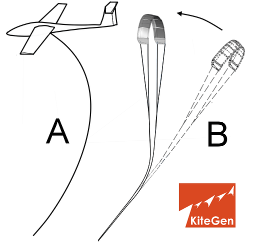
During the tests, we pushed a wing at 2400m and 65m/s observing no tether drag issues. This demonstrates KiteGen’s right to reject the overly simplistic analysis based on the “system drag” idea that combines rope and wing, which appeared for the first time in the Loyd patent, the validity of which is limited to tethered aircraft (A) equipped with a tail that drives and forces the pitch.

Thanks to in-depth research and simulation, it has been established that the drag of the rope is irrelevant to wing speed and energy production. It is, instead, simply a geometric dynamic, conceptually affecting the path in airspace only (B). Tether drag only limits the crosswind motion distance that can be achieved in one stroke, before the wing has to change direction. This is a feature that could be successfully exploited by the control in order to extend the wind power spot.

Issues related to transverse wave propagation on the rope. The wing is typically set to fly at 80 m/s. When the wing changes direction, a new displacement transverse wave acts upon the rope, while the axial wave is running at 270 m/s. Such a transverse wave is slow, due the air mass added to the rope’s linear density, taking several seconds to affect the entire rope. Thus, the wing has the freedom to fly for a few hundred meters before the rope bending will change its optimal angle toward the wind. The models adopted in literature expose an excessively tight time boundary or even a snapshot to track such behavior.

Rope drag is applied axially to the wing, the same effect that gravity has on gliders, that obviously never slows the aircraft. The force vector representing the drag of the ropes binding the wing is only manifested axially, thus thrusting the wing as with gliders. (above picture B case)

As Gustav Eiffel taught us, the Reynold number of the segment of rope near the wing reaches a high value where a new effect called the “drag crisis” takes place, greatly reducing it.

The tether drag issue is speculation based on a fixed cylinder in a flow experiment setup, with a measured coefficient ranging between 1.2 and 1.5. The ropes are light in specific weight which means they are locally free to oscillate and rotate on the axis, dynamically losing air pressure accumulation, thus they cannot be compared to a typical fixed cylinder in a flow.

Larger scales create a lessening of the significance of the issue; this due to the rope section and Reynolds surface ratio, rope section is squared function of the diametre and the drag surface is linear, an advantage that grows dramatically with increasing scale.

The scientific committee of KiteGen published an article trying to explain the limits and errors of the proposed models in the literature review, unfortunately no skilled audience.

Furthermore, in order to gain more flight freedom, KiteGen patented ropes that were appropriately tapered in order to reduce the drag coefficient to 0.03, instead of the classic 1.2 of a cylinder immersed in a fluid that the ropes are immersed in as well. This patent applies to the domain of possible and potential future enhanced optimization of the technology.

To repeat, as this is an extremely important concept, because the production of energy depends on the square of the flight speed, the drag of the ropes is not added to that of the wing, which remains free to fly at the speed of its glide factor or aerodynamic efficiency."

For me it is quite new. Thanks for your observations.

1 Like

Posting by Massimo from kitegen - Interactive Commentary on " Improving mid-altitude mesoscale wind speed forecasts using LiDAR-based observation nudging for Airborne Wind Energy Systems "

1 Like

Hi @Massimo could you precise some point on page 14. For example with a machine’s diameter of 1.13 km, the rotor, the stator, the electromechanics weights are given for respectively 5000 tons, 7500 tons, and 200 tons. Please what is the expected weight of the structure supporting them, onshore, offshore? Thanks.

http://www.kitegen.com/pdf/dossierkitegenen.pdf

I would add that 50 MW/12500 tons rotor and stator lead to 1 MW/250 tons. So this generator looks to be very heavy compared to current wind turbines or other AWE planned generators. Adding the structure to support it. The involved costs could brake or even stop carousel development or direct it towards other solutions.

And they still could not figure out that BOW kites (where the second generation had been on the kite surfing market for over 5 years already at that point) is more efficient than C kites…

I don’t know what they are doing now, I couldn’t find any info or video of their system in operation when I looked into that a while ago, but this - completely depowering the kite to reel it in by shortening one line compared to the other - doesn’t seem possible to do with a bow kite, although it looks sketchy to me regardless so maybe they’ve abandoned that: https://youtu.be/0y-KGi8g94c?t=443 (at the 7:23 minute mark.)

Yes Pierre I somehow got sucked into that discussion on Linked-in too. I advised Massimo that I did not realize they were that far along and they should consider a building a smaller version. He said something about too many forces trying to hold back their technology and prevent them from moving forward.
This is very typical for efforts to develop new types of wind turbine.
There is always this push to build things way way way bigger than a proof of concept would require. To me, it’s a convenient excuse, to conveniently not do anything. It seems to me that if any team with a lot of funding really believed in their concepts, they would jump at the chance to build a small one, which would then work so well that world would demand a larger one.
For people who say they want to replace hardware with software, well, go ahead - what’s stopping you? Build at a scale you can manage easily and prove your concept at a scale you can achieve. This whole drama has been going on for so many years now. Oh well, same old thing, different day… :slight_smile:

Yes seems really risky to just flag out the kite and hope it is pulled in fast enough that it does not just fall to the ground and that it starts flying again when it reaches the bottom of the pull in phase and they tighten up the other lines again. But i guess they would have to do something like that because the depower range is so small on a C-kite. So really just another point in favor of a BOW kite with its much larger depower range while it is still flying.

1 Like