Kyushu University towing tests

Dear fellow researchers,

I would like to invite you to check out our open access publication in the journal MDPI Data:

M. A. Rushdi, T. N. Dief, S. Yoshida, R. Schmehl: “Towing Test Data Set of the Kyushu University Kite System”. Data, Vol. 5, No. 3, 2020. doi:10.3390/data5030069

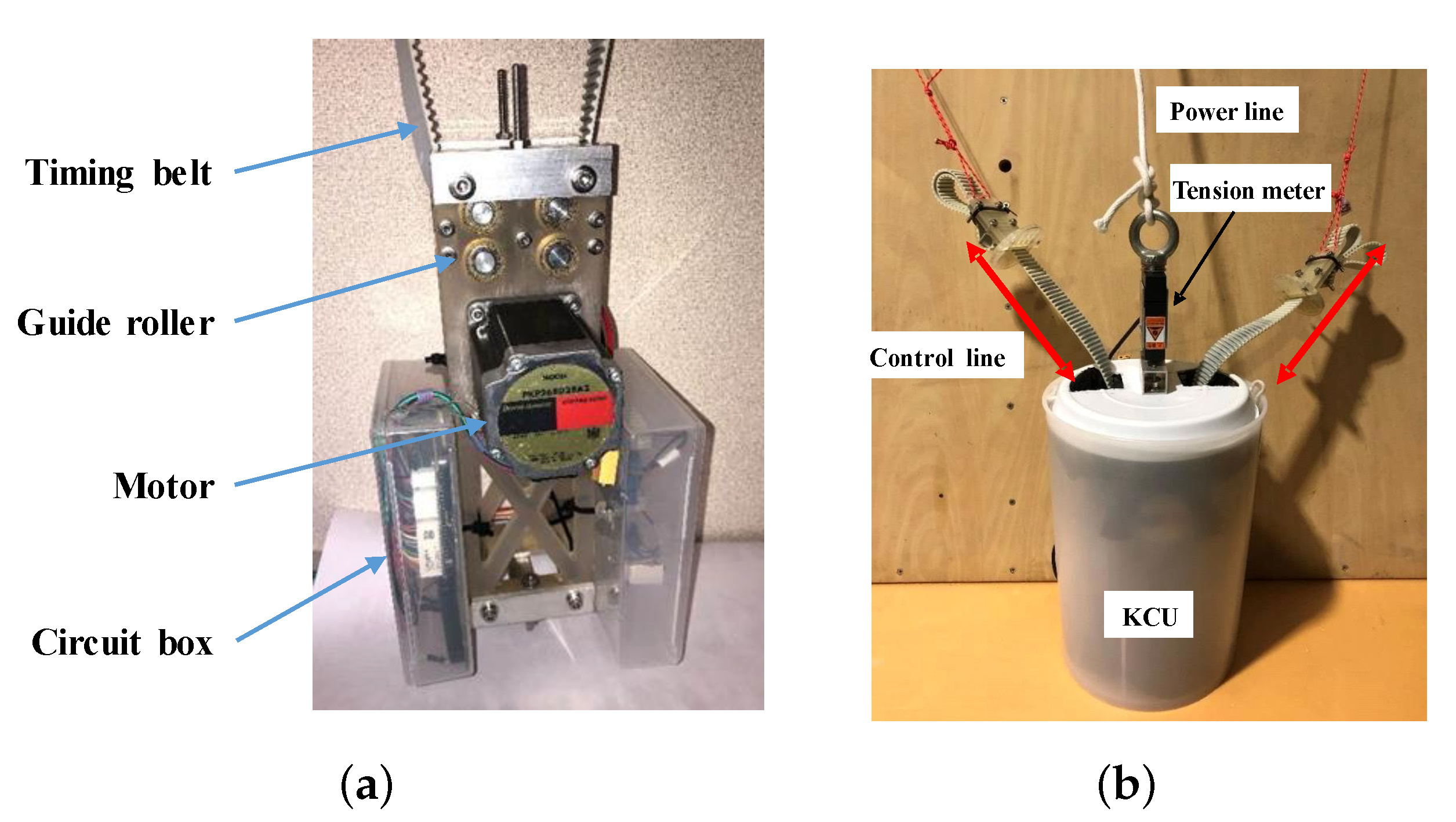
This paper describes in detail the towing tests with a kite using a suspended kite control unit (KCU), the experimental setup, the acquisition of the measurement data, etc. Results should be reproducible, and can be used for validation of physical models.

The dataset itself is available from:

M.A. Rushdi, R. Schmehl, T.N. Dief, S. Yoshida, D. Fujimoto, K. Sawano: “Towing test data of the Kyushu University kite system”. 4TU.Centre for Research Data, Dataset, 2020. doi:10.4121/uuid:c3cee766-2804-4c00-924f-8a9f6c8122fc.

A study on the use of the dataset for prediction of the tether tension using machine learning has been published here:

M. A. Rushdi, A. A. Rushdi, T. N. Dief, A. M. Halawa, S. Yoshida, R. Schmehl: “Power Prediction of Airborne Wind Energy Systems using Multivariate Machine Learning”. Energies, Vol. 13, No. 9, pp. 2367, 2020. doi:10.3390/en13092367.

1 Like

There is a typo on the towing speed graph. It says m/s should be kmh I believe…

Also I could not figure out what you mean with roll, pitch, yaw… I am having trouble seeing how a C kite can roll, being supported by a triangular bridle. I believe a figure could express this more directly

Thanks for sharing

The figure 6 from Energies | Free Full-Text | Power Prediction of Airborne Wind Energy Systems Using Multivariate Machine Learning describes the Kite Control Unit (KCU). These indications provide some elements about how the kite is controlled.

The ground equipment included the wireless unit receiver, a speed sensor and tension meter accessories. The KCU design and its functional components are illustrated in Figure 6. The mass of the KCU, including the Lithium battery, was about 3 kg. The KCU was located 13 m below the kite and used a servo motor to actuate the control lines by which the kite was steered on a specific flight path. The employed bridle layout is common for small surf kites and supports the leading edge tube at four points, and the rear ends of the wing tips are connected to the control lines. The kite is steered by asymmetric control input, shortening one control line while feeding out the other line. Such control input leads mainly to a deformation of the wing by spanwise twisting, because the front bridle largely constrains a roll motion of the wing when the power line and the control lines are tensioned. The wing twist and the modulated aerodynamic load on the wing tips induce a yaw moment by which the kite is steered into a turn [44,45]. At the current stage of the project, it was not possible to actively control the angle of attack of the wing, however, the length of the control lines could be varied along different flight tests. The KCU receives the control action for the servo motor wirelessly from the RC. The KCU was connected to a tension meter which measures the generated pulling force during testing. The KCU was powered by a Lithium battery which could sustain almost three hours of continuous operation. The power line and the tether used in the experiment were made of Dyneema® designed for a maximum force of 2500 N.

Figure 6. Design of the KCU, including structural frame, transmission belts, electronic circuit and motors. ( a ) The core of the KCU without casing and ( b ) after putting the casing on.

Thanks, @tallakt, for pointing this out. It should have been km/h!