Windlift has a similar technology but remains at reasonable scale.
Windfall for Windlift…
I think Windlift is the missing link between the small but efficient Wing4e and the overly heavy M600.
I was getting right into studying the fairings on the tether and bridle
But then the last minute of this video is black

From what I remember there was a ground power overload (They were kicking out a lot on this test) and the power up the tether was cut from the base station. You can still hear the commentary.
It’s odd, looks like the (large) tether fairings are set on the tether really firmly and use an aerodynamic force to align.
Some freaky sideways flying in this vid, the camera angle is great.
There are 2 other camera angle of the incident.
This one

Really shows the shift in balance between the frame and bridling through the last few loops.
Great to have the control audio too really reference each point from
1 Like
I think they should have waited with the fairing tests until they had the rest under control. But now that they did it, it does seem to work. There are some other fairing videos from the bridle where the fairings went into oscillary pitch angle.
1 Like
There had been some work
20161214 RPX-02 - Visualizing Airflow with Tufts
and analysing side-slip
One thing really bugging me is the pylons don’t seem to match the overall asymmetry built for encouraging rotary flight… Maybe I’m seeing them wrong
Perhaps Makani’s fruitful contribution…
Is it about this video?

Sorry yes, edited and added the link into my post now
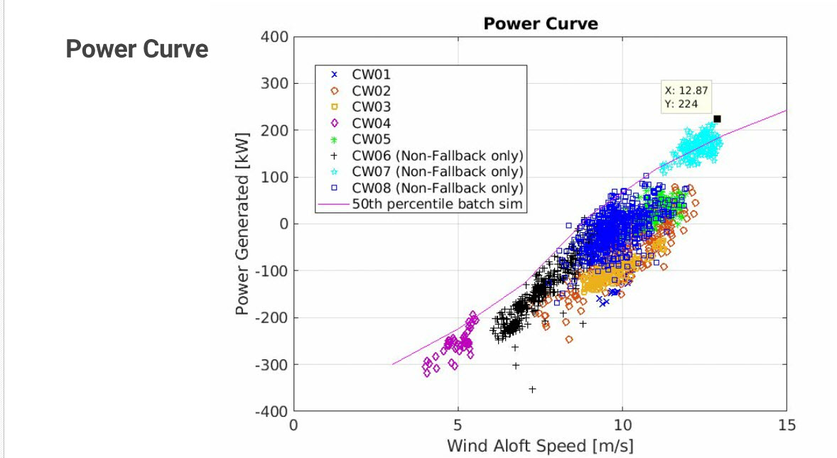
The video below shows a largely positive generation with about 12 m/s wind speed. We can deduce that it would be the same with lower winds for a lighter wing.
The robustness issue could perhaps be mitigated with the implementation of other structures such as the biplanes developed by KiteKRAFT.
2 Likes
CE-07 was the peak configuration performance
From page 285 of report part 3
If only I had 10th of the data in this 1 report for Kite Turbine performance analysis.
As beautiful as the data is. This is hard science time.
So in the words of Richard P. Feynman
First you guess. Don’t laugh, this is the most important step. Then you compute the consequences. Compare the consequences to experience. If it disagrees with experience, the guess is wrong. In that simple statement is the key to science. It doesn’t matter how beautiful your guess is or how smart you are or what your name is. If it disagrees with experience, it’s wrong. That’s all there is to it.
1 Like
Taking over the Baton from Makani points some issues related to the bridle tether connection:
Makani’s kite was susceptible to “roll excursion” in hovering. This was likely the most severe problem of the concept and led to several crashes or almost-crashes of small and large kites.
Makani used a Y-bridle tether connection at the kite which in principle should give a restoring moment for any roll excursion, both in crosswind flight as well as in hover.[…]
In the technical report https://storage.googleapis.com/x-prod.appspot.com/files/Makani_TheEnergyKiteReport_Part1.pdf p. 26, 59 as well as 253 and following, further challenges of Makani’s kites are explained. It provides a justification for the low power generation efficiency.
So there is matter to discuss about the real importance of the Makani’s Y-bridle tether connection as “a justification for the low power generation efficiency”, and also concerning crashes.
Are there not more fundamental structural causes resulting from the weight in flight and the stress on the wing?
1 Like
Exclusive: Airborne Wind Energy Company Closes Shop, Opens Patents
Former chief engineer of Makani speaks to Spectrum about energy kites and the future of AWE
Don’t take Makani’s word for it, though, says Echeverri. Not only is the company releasing its patents into the wild, it’s also giving away its code base, flight logs, and a Makani flyer simulation tool called KiteFAST.
“I think that the physics and the technical aspects are still such that, in floating offshore wind, there’s a ton of opportunity for innovation,” says Echeverri.
One of the factors the Makani team didn’t anticipate in the company’s early years, she said, was how precipitously electricity prices would continue to drop , leaving precious little room at the margins for new technologies like AWEs to blossom and grow.
“We’re thinking about the existing airborne wind industry,” Echeverri said. “For people working on the particular problems we’d been working on, we don’t want to bury those lessons. We also found this to be a really inspiring journey for us as engineers—a joyful journey… It is worthwhile to work on hard problems.”
Makani was the future of AWE ![]() .
.
1 Like
Anyone been able to get the Makani code running from git?
I’m getting a build error from bbuild_x86
1 Like
Part I page 230 table 1, some data: 32.9 m² wing area; 25.66 m wing span; 1.28 m mean aerodynamic chord; 1730.8 kg mass; 2.5 coefficient of lift; 0.3 coefficient of drag (including tether)…
The original design intent specified a full system mass of 919 kg.
The mass has almost doubled. Things would have been different with the originally planned mass.
Just released: the Makani sizing spreadsheet
2 Likes
Also Part II page 43:
Power Systems
● Aerodynamic leverage of kite enables
high speed direct-drive units with high
power density
● Permanent magnet motor/generators
(5kW/kg) and (22Nm/kg)
● 1700VDC SiC controllers with high
bandwidth comms and fault handling
● Medium voltage DC power through
tether is converted to AC on the
ground
● Powertrain units easily field- swapped
and bench-tested
5 kW/kg, so 120 kg for 600 kW motors/generators, in addition to M600 airframe: rotors and spinners = 65 kg (page 20), so 185 kg.
Indeed
The Spreadsheet Kite Structure Sizer
A guide to how the sizer works and how to use it
Florian Kapsenberg, Dec 2019
is available from page 273 of said Part II.
2 Likes
OMG that’s detailed.
Be careful looking at that spreadsheet if you were ever insecure about you’re AWES engineering efforts. You’ll need at least 3 screens to take in enough relevant factors at once to see whats going on.
Just how scuzzy is my engineering work in comparison? I crayoned some squiggles, poked a calculator, stitched some rope and flew toys in comparison to this.
This post shows how relatively short Daisy specs have been…
Just humbling again to see such incredible work processing.
Makani folks really went for the win in a big way. Massive kudos.
2 Likes
The gyroscopic effect of turbines in flight (working a little like flywheels) can also induce some resistance during the figure. Has this effect been identified and calculated?
1 Like
Page 83 of part 1 of the report lists gyroscopic precession as a concern
■ Dynamic loads
● Pylons:
○ Centripetal loading introduces significant bending and (because the powertrains
are forward of the aerostrut) twisting loads on the pylons
○ Stiffness should be so as to avoid whirl-flutter modes at expected flight speeds
○ The motor mounts and bearings experience significant structural loads not only
from thrust, but also
■ Lateral due to centripetal acceleration
■ Lateral due to pylon vibration and twist
■ Lateral and overhung moment due to off-axis inflow
● Requires a sophisticated higher dimensional propeller analysis
that takes lateral inflow into account and produces not only thrust,
but overhung moment as outputs
■ Overhung moment due to gyroscopic precession from body angular rates
■ Overhung moment due to gyroscopic precession from vibrational angular
rates
2 Likes