Hi All - not sure where (if anywhere) this should go…Perhaps a new topic “the Importance of Being Darrieus”?? but this seemed as good a place as any. I must I do approve of the software position - but only as far as it applies to keeping things as tensile and/or inflatable as possible - though that may simply down to my limited computer skills. Anyway…here are couple of videos. Just to elucidate, the windspeed was (according to the Met Office) around 14 mph, and I’d estimate the flying angle (from horizontal) at a little under 45 deg. There’s no generator - it’s just happily spinning. (The parafoil was, as you may notice, not feeling quite as happy - must reinforce the central divider!) - haven’t a clue as to how much power the vertical blades are contributing - as opposed to the considerably smaller horizontal ones - but I’d be surprised if they were just there for the ride. What one should try to imagine is this as one of the central cells of a much longer Darrieus-like construction running along the tether - I’m thinking that as well as doing away with the cosine effect, this might also help to deal with the torque transfer problem, as the blades would taper down to the hub at the bottom.
This would be the case if the Darrieus turbine was placed horizontally and facing the wind. On the video we see that the axis of said turbine is the tether. As a result the cosine effect decreases (and the efficiency increases) as the elevation angle increases, unlike a HAWT if its axis is also the tether. However I see there are both VAWT and HAWT blades, so the cosine effect could be lesser in practice as quoted…
Interesting, waiting for some measures. If the generator is not still available a Prony brake or an electronic steelyard could help to measure the torque.
I think getting away the cosine effect takes more than just ignoring that you have a huge lifter kite. The lifter will be part of the complete rig, and if it is big enough, it will affect the overall cost and handling requirements.
I am not sure if the cosine effect is possible to remove. If you were to remove it, I guess it would involve pointing some forces upwind. Though I believe the fundamental requirement for wind power is to have a difference in air/ground medium speed, and then some way of generating an upwind force which is large enough. If the tether, like in this last video, is mostly vertical, the force cant exist…
Yep interesting system and deserves its own forum thread.
I like that the lifter has 2 lines to hold it down.
Is that also a spreader high up on the spinning line to avoid line twist affecting the lifter. Cool.
There is quite a lot of passively rigid material in the beams and crossed axis blades.
Worth study.
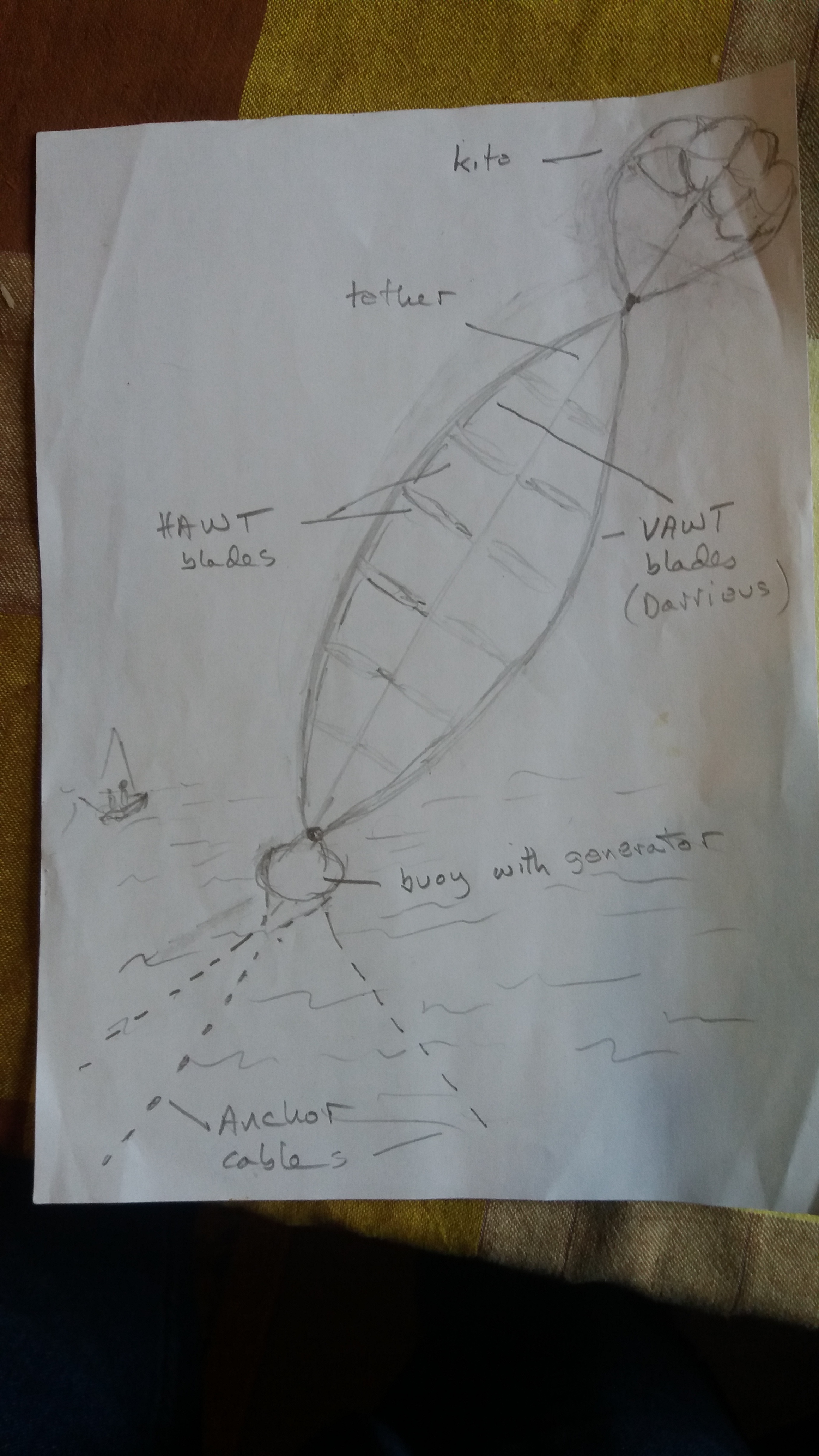
Thanks for the replies - here’s a little sketch to elucidate where I think I might be going…
I’m not sure as to how much “horizontal” blade as opposed to “vertical” blade would be optimal…I’m thinking that the ratio should be such as to make the power output relatively indifferent to the flying angle, say in a window of 30 - 60 deg. As to the size of the lifter kite(s) - I believe the horizontal blades will be creating their own force parallel to the tether (that’s certainly been my experience when the transmission tube has failed and they going spinning up to the kite) - presumably in inverse relation to the flying angle, thereby (hopefully) reducing the required size of the lifter.
Rod - yes - there is a little spreader there - which may have the effect you suggest - though in fact I find one helpful to avoid the kite-line deciding to twist even when there’s no turbine! You’re right - there is a good deal of rigid material aloft - I’m not sure just how much is essential - I take it that a Darrieus configuration aims to throw as much of the turbine as possible into tension - with the centrifugal force of the spinning turbine minimising the compressive/buckling forces in the spars.
As for storms/overspeed protection - I would try to have as little software dependence as possible - with both the kite and the turbine responding to excessive windspeed by partially collapsing towards the tether.
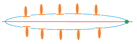
The red line is a lifter line (and should be at an angle). To the left should be a generator and to the right lifter kites. You can make the green oval with the blades wider and narrower by shortening and lengthening the lifter line.
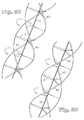
There are some similarities with @dougselsam’ SuperTurbine ™ which mixes HAWT and VAWT (see the figure 52 and the following).
On the videos the TSR seems to not be very high. So the wind force (then the power) on the turbine can be limited, favoring a higher elevation angle. If the whole turbine is optimized, a huge lifter kite would be required, considering also that HAWT can provide some lift, but not VAWT.
Thanks Pierre - yes - I am aware of similarities with some of Doug’s designs - I did have a bit of correspondence with him a couple of years back - though I hadn’t seen the particular figure which you mention. As far as I can gather, Doug has not had very much enthusiasm for VAWT designs recently. His designs are very elongated - with blades of a metre or two in length extending tens if not hundreds of metres along the tether. I am thinking of some less stretched out - maybe 10:1 length to diameter. The helical arrangement of the VAWT blades is interesting, I guess that would be form the turbine would strive towards if the torque was being transmitted down the blades.
As for the TSR - yeah - it’s not great - not sure how much is down to the design/flying angle and how much is due to the rather ramshackle nature of the construction with various bits of string and less than ideal aerofoils.
Thanks,
Philip
Both VAWT and HAWT sweep a partially common area. Perhaps using only HAWT (as for SuperTurbine ™) or only VAWT can lead to a better efficiency and saving material.
Yes - that’s true enough - if one takes it that this is basically a VAWT, the question is how much of an HAWT component is necessary to achieve self-starting and, possibly, to generate lift. Given that spars of some sort are needed to carry the VAWT blades, it would seem to me that configuring (maybe some of) these spars as aerofoils would be a reasonable trade off. I might just say that I did start thinking about this from the VAWT rather than the AWES perspective - ie. what are the problems in extending a Darrieus turbine upwards?
The green part of the oval would be (dyneema) line, the filled orange ovals would be blades, the orange lines would be rods (which might be airfoil shaped) connecting the blades to the line. In operation doing torque transfer I imagine that the line would have that oval – or troposkein – , and helical shape. Perhaps it might be a good idea to stagger the blades between the different lines. An alternative might be to have the blades be more of a paddle shape, with the end of the “paddle” handle attached to the lifter line and able to pivot. Easing torque transfer but limiting the maximum width of your helix.
I think perhaps the top of the oval is fixed to the (red) lifter line and the bottom is not. When you then let out the lifter line the oval becomes narrower, when you reel it in it becomes wider.
Considering that the VAWT and HAWT have the same tilted axis (the central red tether), the green oval could be a rigid or flexible (for lightness) troposkein shaped VAWT, the orange ovals being the blades of the HAWT that are fixed on said VAWT, the TSR of the HAWT being higher than that of the VAWT.