@rschmehl shared some research
https://www.researchgate.net/publication/385813861_Power_curve_modelling_and_scaling_of_fixed-wing_ground-generation_airborne_wind_energy_systems
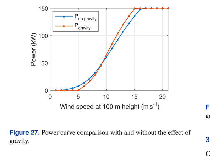
Fig 27: I dont believe this for a second. What scale are we talking about here? No way low wind power looks this good, or the simulation is off. Eg Ampyx AP4 4 ton weight at 100 sqm.
We need to stop wishful thinking in AWE.
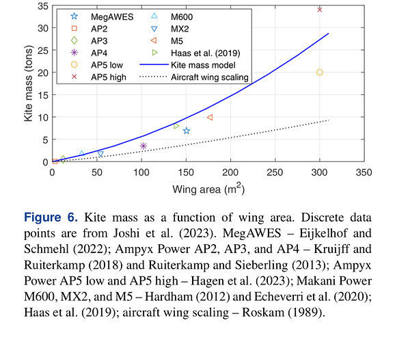
The plot figure 6 is useful and interesting though.
Square cube law swiftly disnissed it seems. And areas of 350 m2 considered. For AR 15:1 that would mean a 73 m wingspan. That is approximately 10x Kitemills KM1…
Note: I did not yet read it top to bottom. But with that fig 27 reading is slightly lowered in my priorities
I did a bit of a follow up questioning on LinkedIn
Roderick Read • You
#KiteTurbine — Kite Power Scaling using Blade Networks — Optimal blade size for real world Airborne Wind Energy
](https://www.linkedin.com/in/roderick-read)
17h
Would you say that the study suggests we have to size AWES wings appropriate to the expected operating wind speeds?
Also… Is avoiding centrifugal acceleration compensation issues by using dual or multi kite approaches more likely to enable scaling?
Like
Reply1 Reply1 Comment on Roderick Read’s comment
Rishikesh JoshiAuthor
Wind Energy Systems | Energy Markets | Optimization | PhD candidate @TU Delft
](https://www.linkedin.com/in/rishikeshsjoshi)
1h
Indeed, the designed AWES will have a good capacity factor if it is sized considering the operating wind speeds. Moreover, better sizing would be achieved if it were designed for LCoE and not just CF. We have a follow-up study currently in the review process exploring design for LCoE, which has more sizing-related insights! Stay tuned ![]()
The multi-kite approach could help counter each other’s centrifugal forces, but this might build up more stresses in the structural links connecting these kites. However, since I have not investigated this properly, I am unable to conclude about its effect on overall scaling.
Like
1
Reply
I dont agree a better approach. Another approach though, I could attest to. I see a product with a poor power curve to be better than one producing eg. only force. I think though this is getting off topic
I think the scaling law here is varying roughly between square and cube, just like for wind turbine blades on:
Technical Data
Model Rated Power Single Length Chord Wide Single Weight Start wind speed Rated wind speed Rated rotor speed Safety wind speed HB-1.2 500W 1200mm 160mm 2kg 3m/s 10m/s 300rpm 40m/s H-1.17 500W 1170mm 170mm 2.3kg 3m/s 10m/s 300rpm 40m/s HB-1.34 1KW 1340mm 170mm 2.6kg 3m/s 10m/s 300rpm 40m/s HB-1.35 1KW 1350mm 200mm 2.6kg 3m/s 10m/s 300rpm 40m/s HB-1.55 1.5KW 1550mm 240mm 3.5kg 3m/s 10m/s 300rpm 40m/s HB-1.6 2KW 1600mm 230mm 3.6kg 3m/s 10m/s 300rpm 40m/s HB-1.9 3KW 1900mm 250mm 6.1kg 3m/s 11m/s 220rpm 40m/s HB-2.28 3KW 2280mm 315mm 16kg 3.5m/s 11m/s 230rpm 40m/s HB-2.31 3KW 2310mm 315mm 13kg 3.5m/s 11m/s 230rpm 40m/s HB-2.49 5KW 2490mm 330mm 13kg 3m/s 11m/s 220rpm 40m/s HB-2.6S 5KW Stalled 2600mm 300mm 7.5kg 3m/s 14m/s 250rpm 50m/s HB-3.1S 5KW Stalled 3100mm 310mm 10.2kg 3m/s 13m/s 180rpm 50m/s HB-3.2 7KW 3200mm 450mm 34kg 3m/s 12m/s 220rpm 50m/s HB-3.5 10KW 3500mm 400mm 32kg 3m/s 10m/s 200rpm 50m/s HB-3.8F 10KW 3800mm 400mm 35kg 3m/s 10m/s 180rpm 50m/s HB-3.8P 10KW 3800mm 400mm 36kg 3m/s 11m/s 180rpm 50m/s HB-3.6 10KW 3600mm 520mm 46kg 3.5m/s 12m/s 220rpm 50m/s HB-4.5 15KW 4500mm 500mm 66kg 3m/s 10m/s 180rpm 50m/s HB-4.795 20KW 4795mm 542mm 82kg 3m/s 11m/s 160rpm 50m/s HB-5.885 30KW 5885mm 830mm 150kg 2.5m/s 10m/s 90rpm 50m/s HB-7 30KW 7000mm 830mm 165kg 2.5m/s 11m/s 90rpm 50m/s HB-8.17 50KW 8170mm 1150mm 240kg 3m/s 10m/s 60rpm 50m/s HB-9.065 80KW 9065mm 1025mm 260kg 2.5m/s 11m/s 60rpm 50m/s H-10.5 100KW 10500mm 1035mm 280kg 2.5m/s 11m/s 60rpm 50m/s
For these examples for an assessment of mass scaling, the dimensions are taken in first, before the given power value for which the Reynolds number can be considered, favoring the large rotors.Two-by-two comparisons:
3500 mm, 10 kW, 32 kg; 10500 mm, 100 kW, 280 kg. 32 kg x 3² = 288 kg: mass squared (and not cubed) scaling roughly applies. 10 kW x 3² = 90 kW.
2600 mm, 5 kW, 7.5 kg; 10500 mm, 100 kW, 280 kg. 7.5 kg x 4² = 120 kg, and 7.5 kg x 4³ = 480 kg: between mass squared and mass cubed scaling. 5 kW x 4² = 80 kW. 5 kW x 4³ = 320 kW.
1200 mm, 500 W, 2 kg; 4795 mm, 20 kW, 82 kg. 2 kg x 4² = 32 kg, and 2 kg x 4³ = 128 kg: between mass squared and mass cubed scaling. 500 W x 4² = 8 kW. 500 W x 4³ = 32 kW.
If we remove the heavy parts (the base having to engage with the hub is not useful as such) like @Rodread did, perhaps there would be possibilities with aerostats, in addition to Daisy. But rigid wings for crosswind flight…
The figure 6 suggests that there could be plans to fly kites weighing almost thirty tons. And we know that there have been dismal failures with masses of one tenth.
And, in the infinitesimal possibility that such a thing could take off, then make a complete figure (kinetic energy preventing the ascent!), the public will never accept being near or even far from crosswind tethered shells.
It is therefore not necessary to go into further detail, although we will be able to appreciate the work that has been done on scalability and according to different wind conditions.


