My point of this post was basically to ask yourself “how gullible are you?”
One “press-release breakthrough” after another.
The solar chimney theme was taken seriously by probably thousands of people, for a few years.
Then what happens?
Has anyone even bothered to build one?
Are any operating today?
Or was it a load of hogwash all along?
How much of what you read is utter hoghwash the whole time?
Just step back and see the bigger picture:
Out of 1000 supposed breakthroughs in wind energy, ZERO emerge as real solutions…
Just sayin’, look at the odds. you better have something good! 
I’d recommend you get out there in a strong wind with balloons having minimal buoyancy and see what happens. Air currents don’t always behave as we wish they would!
Once a slightly positive neutral buoyancy is achieved, the Magnus balloon works like any other kite, except that it cannot fall, or go down (except in thermal or dynamic downdrafts, like any large kite subject to these weather problems). But it gets its aerodynamic lift (apart from buoyancy) from rotation. It can also reverse its lift. So I’m not too worried about that. Omnidea’s balloon flew well under normal conditions. After that it’s a question of adjustments.
Yes key concept: “flew well under normal conditions”
“Normal” meaning “optimal”.
Just to keep track of power usage: We’re now sending electricity UP the tether(s) for:
a) heating the interior air
b) rotating the tubular balloon envelope to generate lift
Now I don’t want to throw cold water on a possible breakthrough, but this is just reminding me of wannabe inventors “rescuing” the vertical-axis concept. It’s all about adding “band-aids”, each of which has SOME downside. In this case, before we receive any power, we’re sending power up the wire, now for two (2) different purposes.
And don’t forget
c) the electric heaters and the rotation motors add weight, which requires more power to be used
So we should bear in mind we are adding complication, weight, and finding ways to use power before any is generated. Still, if it works well, so be it. Just pointing out, power being used is not desirable in general.
This seems to tend toward falling into the “all ya gotta do is” category
All ya gotta do is add motors, add power, add heaters, add more power… (?)
Dave Santos noted with the link of a video below:
In sailboat racing, a key competitive edge is speed-tacking. In many Kite Sports, fastest turning is a critical advantage. In crosswind AWE, a fast-turning kite operates in a more compact airspace and minimizes transition phase between crosswind load-driving directions. Kiteplanes turn far slower, so they easily overshoot the Power Zone in large loose patterns with far lower power-to-mass, and far worse scaling, plus lowest safety-reliability at highest capital cost.
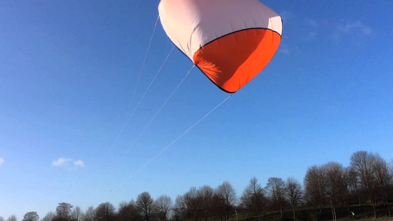
I couldn’t agree more. Except that “fast turns”, that sounds good, but “no turns”, that is even better.
Perhaps 1/10 the weight of the balloon. Not a major problem. Omnidea’ balloon flew with the motors, and used helium to achieve minimal buoyancy, and achieved a good average net power. I want avoid helium. Note that here the extra-weight adds buoyancy, unlike kites which must takeoff and land more often. And don’t forget the major key in AWE: the ability to scale up.
In regards to the drop stitch or carbon fiber rings idea: you wouldn’t be able to produce drop stitch rings for your prototype, and wood would be easier and cheaper than carbon fiber, and environmentally friendly.
There is also no need to use drop stitch fabric, even if you could produce it. You use drop stitching to create flat boards that don’t bulge out when you inflate them to a somewhat high pressure. That is not needed here.
Instead, for example, you’d add mounting points to the outside of your envelope and to those attach an inflatable torus, inflated to a reasonably high pressure, and to that torus you’d attach short, probably oak, segments with a groove for the belt cut into them. You’d have channels in the oak segments to route a somewhat elastic rope through to post-tension them. This would work somewhat like, or maybe a lot like, a tensairity ring.
1 Like
Forgive me if I’m wrong
Been skim reading
@PierreB was proposing a huge double skinned cylinder
So a normally flat double wall material concept like Dropstitch would have little compression on the inside skin given the large radius.
You’d likely want to specify a low density of drop lines?
Drop stitch technology can be useful and strong enough to realize full double discs (for more rigidity) or crowns (if possible for saving material) comprising tracks for the belts settled between the respective discs or crowns. They need to be under fairly high pressure (as for drop stitch paddles) to support the tension of the belts , while the balloon as a whole remains at barely above normal pressure.
A part from the double discs surrounding the balloon, the envelope is a simple ripstop envelope, like that of a hot-air balloon, which is what this balloon ends up being with the electric heater to gain few degrees.
Because of that, this is randomly picking an option and not a considered choice. You should really do some analysis or even some basic literature research, if this was anything more than idle musing, on this, and of course the rest of the concept:
Unless you mean a solar balloon with added heating.
An approximate mean to calculate the required power for heating:
See at “thermal insulation properties of ETFE Film Structures”: “U-value (W/m²K)” where U-value is a coefficient of insulation. By this formula the area (m²) is considered, not the volume (m³).
W = U-value (m²K).
I think you have omitted an important design parameter. The cylinders mus be overpressurized (pump and more air density) or have a compressive member (mass) to keep the discs apart to allow your cylinders to transmit moment. Depending on your choice here, the added mass could be calculated.
The pressure within drop stitched elements is significantly higher than the atmospheric pressure, so than the pressure within the simple envelope which is inflated at an atmospheric (a bit more) pressure by fans aloft located at the two ends. The drop stitch double discs can be full or like wheels of bicycle, with drop stitched spokes. But simple crowns (far lighter) can be sufficient to save material. However crowns will don’t prevent the deformation of the simple envelope. If the deformation is not too important thanks to the wideness and length of the belts, double crowns could be a possibility.
Your “cylinders” = the balloon? The balloon is a simple envelope surrounded by double discs.
In Magnus effect and by pumping mode, the balloon transmits pull, not torque. But motors transmit torque in order to rotate the balloon with the belts settled between the respective double discs.
I was going to suggest burning gas for heating like real hot air balloons, but then I realized I had almost forgotten to mention my favorite lifting gas: methane. (natural gas)
About half as effective as helium or hydrogen, still plenty of lift.
A bit more than half the density of air.
Bigger molecules = less leakage
You can still use it for other things when you are done demonstrating AWE
You could also burn natural gas in engines to spin the balloon
Methane is good, but is inflammable. And gas lighter than air needs maintenance and add costs.
I don’t need enormous buoyancy. Don’t forget that in pumping mode you have a descent phase, and this phase is made more difficult when the balloon has enormous aerostatic thrust (buoyancy). A slightly positive neutral buoyancy is more suitable.
The natural physics of what you suggest is to collapse the cylinders lengthwise. So you need some force to keep the end discs apart
Again, I don’t know what you refer by using the term “cylinders”. Is the cylindrical envelope I call balloon? Are the double discs or crowns? And please specify your question.
I was referring to each segment of balloon between the tethered sections. There is no force described yet to pull the 1 km magnus cylinder [balloon] lengthwise.
Such a long cylinder (stack of cylinders) will not be entirely straight either. So there must be some space between the cylindrical segments to allow for deformation? How does the gap interfere with the magnus effect?
These are in my opinion really hard to solve
In the current Magnus balloon tied by the two ends, there is a potential curvature in the middle due to wind force. This curvature is relatively reduced as the aspect ratio decreases (the Magnus balloon being thicker). And the total force is distributed only on the two ends.
Now, as you indicate, there are several “segments” for their respective tethers. So there are several potential curvatures in the middle of each cylindrical segment.
Thank you for pointing out this issue. I don’t know if I quite understood the challenge.
I think the holding of each segment by the belt surrounding it could reduce a bit the potential of curvature. And for the balloon of 1 km and 200 m diameter, each segment could be 200 m long, leading to a low aspect ratio per segment, so to a low potential of curvature. It depends also on the pressure in the balloon, which is controlled by fans at the two ends.
But I am not sure about what I say.
I don’t know if potential gaps would affect the Magnus effect, and how much.
Yes, well, I just thought I’d mention the possibility of using methane, since I seldom, if ever, see anyone mentioning the fact that it is directly behind hydrogen and helium as far as lift. (When, in all the years of AWE hype, has it been mentioned, if not by me?) You could mix it with air, and hope there is no spark, or use it to explode the whole thing as a safety fallback, although, then again, it might cause a lot of destruction on the ground, at such an extreme size!