Rotating AWE systems can also be seen as crosswind kites flying within a structurally constrained path.
In first here is the link of some last Roderick Read’s R&D for Daisy (https://link.springer.com/chapter/10.1007/978-981-10-1947-0_21) towards a long and thin rotating unity: https://twitter.com/rodread/status/1062351165415981061/photo/1.
My light contribution is the implementation of an horizontal (instead of tilted) ring generator as described on https://link.springer.com/chapter/10.1007/978-981-10-1947-0_22, named Rotating Reel, and shown on https://www.youtube.com/watch?v=Bc2loZC4aD0, allowing more scaling-up in wideness, and also takeoff and landing operations by all wind directions. Expected (but not insuperable) difficulty: the requirement of a very large rotor, probably with flexible SS blades-wings placed end-to-end.
Another rotating system is the KiteGen carousel: https://www.youtube.com/watch?v=Fxo8HofKofY&t=10s.
A main purpose can be the maximization of land and space use as the system is a single system (carousel, rotating reel), or several unities within a network as Rod envisages, or both.
It’s refreshing to read rotary as crosswind.
The path of a Daisy kite on a rotor is exactly analogous to the programmed desired path of the Makani rig. It’s even mor crosswind than a circular yo-yo path with the downwind corkscrewing.
I do not want to constrain daisy kite rotors to short radius paths. Centripetal acceleration and bank angle encourages expansion of the rotor. This expansion should be exploited to dynamically increase swept area per unit kite as wanted.
This tweet thread https://twitter.com/rodread/status/1062283887974539264
Shows how a stack of networked kite rotors can be dynamically reconfigured with expanded rotors flying a larger swept area.
Also of note is the possibility to hoist rotors under lifting kite networks.
This massively increases the density of deployment over land area.
https://youtu.be/IlslZIg6iUQ
and
https://youtu.be/8mVj2QU_dYc
Similarly hoisting rotors inside tensile lattice volumes would massively increase the density of deployment over a given land area.
https://youtu.be/8vpTF2m4ub4
There should be little doubt that rotating AWE rigs are crosswind just like most other AWE concepts and like traditional windmills. I would think the definition of crosswind would say that the wings are moving mostly perpendicular to the wind, and staying mostly downwind.
I have some Q for you Rod, just out if curiosity. How do you plan to hoist and land your kite network? How will you tackle storms? I would assume that with a rotating AWE system, you cannit easily stay at zenith, and there will be generated power… also stopping the rotation would necessitate the leading edge of your wings tilting quite a lot towards the ground anchor/wind origin…
Btw if you ever consider building the network of rigid kites currently shown on your homepage, Kitemill’s body/kite may work for you. Im sure my manager might agree to let you use them. And you need so many. Using our’s will probably save you time. Just PM me and I’ll put you in touch
Also I dont think changing the radius to increase swept area is a sound plan; whatever the radius, if the centripetal forces are generated by tethers, and the radius is far larger than the wingspan, the wing should fly at the approximate same speed. According to the AWE book i believe the max speed of the kite is something like
v = w G cos x cos y
Where G is the glide number of your wing, x and y are your angles over the horizon and off-wind.
Your best bet for changing the power generated would be changing other parameters than the radius IMHO
Yes, if you are sweeping at a larger area you will catch more wind, but the utilization of the wind will decline also, unless you are affected by the wake of another wing.
I might have missed something here
Maybe this is topical and gives an intuitive feeling of the problem, or maybe not:
I have one more Q: How will the system adapt to changing wind direction if it is tied to the canopy layer on top?
I am not sure to understand why. Please can you explain? Beside it the more the radius is large the more the angular speed is low, leading to lesser centripetal-centrifugal forces as the diameter increases, no?
The centripetal forces are quite small compared to tether force, so they do not make much of an impact.
There is one aspect of a rotating rig that I had not thought about. The radius will of course affect the rotational speed. Longer radius gives you slower rotation. But the power given by P = w M (where w is turning speed and M is the torque/momentum generated) should be fairly constant. Radius must be designed to put a cap on torque (to prevent a collapse of the structure) and getting a w suitable for the generator.
To understand why changing radius is ineffective, imagine that the system is unloaded (zero torque). Each wing will fly at its nominal max speed v=G w cos x cos y. The rotational speed is v=w R. Next we apply some small torque leading to a small slowdown causing a force effectively similar to a drag, lets call it F. The moment applied at the generator M is M=R F. Now the power generated is: P=M w = F v. It should make sense that P does not depend on R.
I made a wolfram one workbook to calculate the power of a rotaty AWE windmill (consisting of rigid wings total surface area 1 sqare meter):
https://www.wolframcloud.com/objects/tallak-kitemill4/Published/radial_awe_power_v2.nb
If seems the power like for single wing AWE is when the speed of the wings are v ~ 2/3 G w, where G is the glide number, v is the speed along the path of the wing, and w is the windspeed.
As you have no drag to speak of per wing, the real limitation of such an AWE rig is really how fast you can fly with your wings before they break, and still have a sensible minimum cut-in speed.
If your G is in the less than 3 range, it doesnt matter how fast you fly, you always get the same power
http://homes.esat.kuleuven.be/~highwind/wp-content/uploads/2013/08/Diehl2013a.pdf and https://windswept-and-interesting.co.uk/wp-content/uploads/2017/12/KiteNetworksWandI.pdf describe the Power Harvesting Factor ζ respectively page 15 and page 523.
IMHO deducing (in a similar way than the rotor solidity of a windmill) that the Power Harvesting Factor ζ of the wings leads to wings area change in regard to radius and swept area changes. But that goes for a single layer. Daisy has several layers.
In Daisy’s configuration all layers should have the same angular speed. So the layers should have the same radius OR the wings should be different. As example a low radius layer would contain slower kites while a high radius layer would contain faster kites, that in order to keep the same angular speed in all layers.
To Rod also:
As the linear speed of the kites is kept the centripetal-centrifuge accelerations decrease while the radius increases. Concerning the “bank angle” some measures would be welcome to know the potential of expansion of the rotor: I guess it can be limited.
But I might have missed something here.
Until we are approaching “zeta” factors that harvest most energy of the swept area, my analysis I think is correct. I also mentioned that the analysis only holds if the kite is unaffected by the wake of the kite in front.
I am not sure AWE should aim to provide higher zeta factors than windmills. While this is a useful calculation to perform, in practice I am not sure whether airspace is a limited resource in the same way that it is for windmills. With AWE you can go higher and wider and capture far more air “area”. Optimizing efficiency may be interesting at a later point.
In the meantime, changing the radius will not give you much in terms of power control. As the power generated is w^3 and your construction has real finite limits, other means of regulating power is most likely necessary.
With regards to banking action, the tension of the tether structure will dominate over the centripetal forces for the kite mass, at least that is my prediction. Banking is indeed a way of depowering the rig, as more of the lift is diverted to forces pointed away from rotation center, thus leasing to an decreased efficient G number. But due to the cosine law, this way of depowering will not be very efficient until the banking angle is >30 degrees.
There is one more way to spill power while actually providing a useful side effect. If the wings bank only when they are on the upper side of the loop, they will lift the structure to a higher altitude than what the lifter kite alone may provide. The lifting will further increase the cosine loss, further causing an indirect depower.
The Rotating Reel system I studied (https://link.springer.com/chapter/10.1007/978-981-10-1947-0_22), video on https://www.youtube.com/watch?v=Bc2loZC4aD0, contains both a large and horizontal (for both easier implementation and adaptation to wind direction changes) ring generator and a large flying rotor that are connected each other. If the ring generator diameter is 500 m the flying rotor diameter can be about 700 m. This configuration can allow a better maximization of the space used.
Flexible wings can be implemented end-to-end to form the rotor. Saving material is possible, keeping only the tips of the rotor, so flexible or rigid wings could be implemented, maximizing almost as much the swept disc area, while generally crosswind kites have their own respective swept areas, being far to maximize the space/land or sea use due to the lack of coordination of their respective swept areas.
As attachment some sketches with hydro turbines as simpler ring conversion system.
Wind generator at sea including kites pulling a rotating annular structure.pdf (300.8 KB)
For 100 kites in a constrained space changing the diameter might work. I believe that once you start flying in the wake of other kites, you might get new issues due to the fact that the top of the rotating AWE rig will se lower wind speeds and this rotate slower. It could be difficult to design the kites such that they all operate at the best aerodynamical setpoint and generate a good power output, even when constrained in speed.
I would guess you want to avoid electric steering for so many kites, some suggesteions for automatic power control could be spring loaded flaps, spring loaded elevator (both affecting AoA), spring loaded ailerons with dihedral (depowering through bank angle), propellers with a breaking circuit (depowering through an extra drag applied)
Let me add that I believe these designs have big potential, just trying to get a grip of what the design issues will be for these rigs.
My previous message with the attachment was a bit confused. So I simplified the attachment:
-
FIG. 1: hydro-carousel, for all options.
-
FIG. 2: hydro-carousel figure-eight that is a well-known configuration excepted the hydro conversion. But (IMHO) the coordination of the swept areas by the wings is not well assured.
-
FIG. 3: hydro-rotating reel with wings as the flying rotor. For example putting four (or more) Kitemill’ wings in pairs.
-
FIG. 4: hydro-rotating reel with a flying rotor (my initial invention studied on https://link.springer.com/chapter/10.1007/978-981-10-1947-0_22).
-
FIG. 5: hydro-Daisy
Rotating reel systems as shown on the FIG. 3 and 4 has variable tethers due the tilted kite disk connected to the horizontal ring generator.
Observations are welcome.
Otherwise some steering means you indicate could be advantageously studied.
hydro-carousel-figure-eight-rotating reel-Daisy.pdf (156.9 KB)
Rotating Reel operations as shown on FIG. 3 and 4 can have a limited linear speed due to hydro-conversion requirement. Indeed an hydro turbine like on https://minesto.com/ can reach 10-20 m/s. Probably a higher speed would be possible, avoiding cavitation concern. As the flying rotor is a bit larger, its linear speed would be about 25 m/s, so below the speed of a flexible (and for stronger reason a rigid) crosswind kite.
For the rotating reel system the “flying rotor and the ground rotor are co-rotating at identical angular speed” (https://link.springer.com/chapter/10.1007/978-981-10-1947-0_22). So the ring conversion should be fast enough, in the same way as Daisy. In the other hand the hydro-carousel as shown on the Fig. 2 doesn’t require a very fast linear speed because the kites fly by figure-eight several times per ground ring rotation.
Hi. I cannot see the «Springer» link as these are behind a paywall. Under the reason of keeping the internet an open place, I am quite opposed to such links. Consider this my private struggle, but also a real practical impediment for people to sharing information.
Now I have been thinking a bit about the carousel and line drag. I read earlier that each kite is only supported by the tether necessary to keep it in the mesh, and therefore the drag is minimal.
I want to propose another point of view that has the opposite conclusion. I think it would be enlightening for us not too deep into these carousels to hear what you think about that argumentation.
I will compare an Ampyx/Kitemill single wing AWE with a similar radial AWE with, say, 6 wings each of size 1/6th. Otherwise the kites are operating at similar parameters (lets assume the same parameters are optimal for both systems).
Now the tether necessary in order to not break should be the same for both systems, the strength of the tether given by the area of the tether cut section. The wings are moving at the same speed (more or less?) and all the line is moving more or less in a cone. If the Kitemill/Ampyx style rig needed a diameter of x mm, the radial AWE rig would need 6 times diameter 1/sqrt(6). The total area of tether facing the rotation would be approx 2.4 times greater for splitting the tether into six smaller tethers like this.
One way to save tether drag is to have a Y split along the tether somewhere. I cant see that the radial AWE rigs have this.
I can only conclude that the rotating rigs have, as a first approximation, more drag than a single tether AWE rig. This will necessitate higher lift, slower, wings. But that is not really a positive thing, because the larger power potential of AWE, I believe, depends on a high G (L/D ratio).
The Springer link I provided is similar to the link you provided under “literature recommendations” topic on Airborne Wind Energy: Advances in Technology Development and Research | SpringerLink. There is a preview of all chapters, but it is not enough. The chapter 22 (authors Dr. Roland Schmehl and me) is partially available on Airborne Wind Energy: Advances in Technology Development and Research - Google Livres.
Here is also the link for the abstract Rotating reeling | TU Delft Repository, and the link for the poster http://www.awec2015.com/images/posters/AWEC25_Benhaiem-poster.pdf. But the chapter 22 is more detailed and correct.
In my opinion the Rotating Reel system is between Daisy and the known carousel.
For the Rotating Reel system the flying rotor works the ground rotor. Both have identical angular speed, but as the flying rotor is tilted there are length variations of the peripheral tethers.
The peripheral tethers have a lot drag on their whole length (at less when the tethers lengths reach the peak value), but perhaps the big size of the flying rotor can compensate it.
In a carousel configuration the tethers undergo much drag due to the apparent wind. So I can agree what you mention if I understand correctly.
Concerning G (L/D) ratio, also discussed on “High lift coefficient and biplane kite” topic, the paper in reference indicates: “…the power increases cubically with CL and decreases only quadratically with CD…”. But the CD increases with the square of the CL, reducing G (L/D ratio) a lot. So “the larger power potential of AWE, I believe, depends on a high G (L/D ratio” (as you indicate) sounds right. Precise calculations can be useful.
Please can you explain, if possible with a sketch?
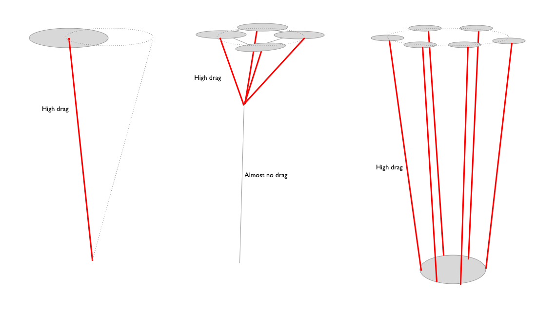
I have tried to show why tether drag could be reduced by using multi wing AWE, but why a lot of the sketches from PierreB and Rodread don’t utilize this possibility.
Also splitting a single tether into thinner N tethers increases the total drag by a factor og sqrt(n) if the movement is otherwise the same.
Now you mentioned I previously linked to the paywall at Springer publications. This is true, but I do think there is a difference between linking to a book that may be purchased in paper/electric form (one would expect this to cost money), and a scientific paper of 20 (?) pages. I originally linked to Amazon, but changed my link to point to the publisher of the book, so as to not lead potential customers to a particular shop. Anyways, this doesn’t matter, the important thing is that I am not reading any text behind a paywall. The reason being A: I am not going to pay for it and B: I don’t want to pay for it, even if the abstract seems interesting
The Springer chapter (22) and the whole AWE book give some abstract(s) and preview(s).The only difference I see by linking the book instead of the desired chapter is that the reader has to go from the book to the chapter, seeing in the end two paywalls instead of only one.
On my previous message I provided some links for more free information but on smaller documents of the same topic, detailing them, or for a bigger free part of the chapter. For example, if I am right, you can read 7 pages (the whole chapter 22 is 40 pages) on the big Google link.
Thanks for your sketches. Indeed both Daisy and Rotating Reel (and also other carousels) use your third sketch, due to the requirement of the torque transmission to the horizontal (rotating reel) or tilted (Daisy) ground ring. The first sketch represents crosswind kites like Makani’, Ampyx’, Kitemill’ and others. The second sketch could be the “dancing kites” studied by M. Diehl and mentioned on http://homes.esat.kuleuven.be/~highwind/wp-content/uploads/2011/09/SADCOseb.pdf, in order to decrease tethers drag. This arrangement is also suitable as it allows a full maximization of the space use, but cannot work a ground rotor. Generally turbines onboard are envisaged for the second sketch.