Scaling Laws in AWES Design

Perhaps flexible AWES could be the only wind devices that can scale almost limitless.

If these observations and some deeper tests are confirmed, this would be a way to explore further some single skin kites, and as a result a possible advantage of AWES over HAWT in regard to density potential and low material use.

1 Like

This comment asks about the possible difference in weight penalty in scaling between static (lifting) and power kites.

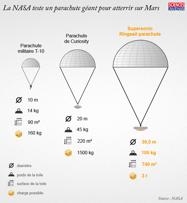
An example about how a parachute can scale (see the picture below from the linked article, easy to read even in French):

There is no (expected) mass penalty as we go from the smaller parachute to the larger one.

Considering Peter Lynn’s observation, it would appear that flexible static kites also do not suffer a mass penalty in scaling.

In contrast Storm Dunker’s paper provides values leading to a significant mass penalty in scaling, page 532:

The development originated as an Advanced Concept Technology Demonstrator
research program from Natick Soldier Systems, whereby iteratively heavier
weight requirements were levied (0.25 ton, 1 ton, 2.25 tons, 4.5 tons, 13.5 tons, and
finally 19 tons). The wing sizes were 36 m2, 102 m2, 250 m2, 350 m2, 900 m2,
and 1,040 m2, respectively.

A few lines later, on the same page:

It is noted that as the wing became larger, a heavier wing loading was used.

These Ram-air cargo wings look like ram parafoil power kites of type SkySails’ wings and for which I do not have elements about how they scale up.

Would it be possible that flexible static (lifting) kites are not subject to a mass penalty, unlike flexible power (ram or single skin) kites? If yes, wouldn’t one cause be the increased difficulty to maintain the required aerodynamic shape for a power kite as it grows, due to highly increased material constraints?

Hi Pierre, I think airspeed is varying differently in your cases. With a kite, the windspeed is not increasing with kite size, so for a same windspeed you need around the same ratio of weight by area. For a dragging parachute, you want to limit the speed at landing, so once again the sinking rate and apparent wind speed will not vary with size, so you need around the same ratio of weight by area. For a glider however, you need to increase the weight and air speed with area in order to keep the same finesse.
Here we can introduce the Froude number which is more famous in ship design but also applies to aircraft design. To get a so called Froude similitude, you need to scale the area with the square of the length, the mass with the cube of the length, and what seems to be forgotten here, the air speed with the square root of the length.

If you were just scaling a kite in three dimension (including cloth thickness), you would need the wind speed to increase at the power 1/2 of scale. However, the wind is only increasing with the power 1/7 of scale (power law wind gradient).

The good news for kite designer is that you can test a design or prototype at smaller scale with Froude similitude just by testing with less wind that at full scale. Let’s say I want to develop a 20m2 model scale for a 320m2 kite (16 x 20m2=4 x 4 x 20m2) to be flown in 20kt of wind. I can simply find the optimal 20m2 wing in 10kt (20/sqrt(4)=20/2) of wind. Usually you stay in the same Reynolds range (for the kite at least, you might have trouble with the bridling).

3 Likes

Hi Baptiste, welcome to the forum @batlabat. This looks correct for what I understand now. Thanks for the information.

1 Like

Thanks Baptiste @batlabat
Really appreciate your clear description on scaling

This is a point I’ve noticed from day-one of such scaling discussions: You make a wind-harnessing apparatus twice as big - everything gets bigger except for one thing: The wind speed. By the time you’ve scaled up an apparatus 10 times as large, with 1000 times the mass, with the wind still going the original, now comparatively slow, speed, the wind-induced stress on the apparatus would be comparatively smaller. This may be one reason why the scaling mass increase for wind turbines has been noted as less than a cubic function of blade length.
Also, to test very small models at higher reynolds numbers, use a water tunnel instead of a wind tunnel.
Of course, AWE people typically don’t know about water tunnels - well now they do. :slight_smile:

PDF available. See the Figure 3:

Figure 3. Masses of AWE systems as a function of the wing surface area. MegAWES [25], Ampyx
Power AP2 and AP3 [20], AP5 low and AP5 high [26], Makani Power M600, MX2 (Oktoberkite), and
M5 [27,28], Haas et al. 2019 [29], and conventional aircraft wing scaling [30].

The curve of conventional aircraft wing scaling looks to be almost linear. An explain page 4/20:

The aircraft wing scaling law (dashed line) is optimistic because it only includes the mass of the wing, omitting the fuselage, tail, and other electronic and electrical subsystems. The correlation provides a reference to compare the mass of conventional, untethered aircraft to that of fixed-wing kites for airborne wind energy harvesting designed for a substantially higher wing loading.

The main purpose seems to be the levelized cost of energy (LCOE). Power to space use ratio does not look to be considered.

Abstract

In the current auction-based electricity market, the design of utility-scale renewable energy systems has traditionally been driven by the levelised cost of energy (LCoE). However, the market is gradually moving towards a subsidy-free era, which will expose the power plant owners to the fluctuating prices of electricity. This paper presents a computational approach to account for the influence of time-varying electricity prices on the design of airborne wind energy (AWE) systems. The framework combines an analytical performance model, providing the power curve of the system, with a wind resource characterisation based on ERA5 reanalysis data. The resulting annual energy production (AEP) model is coupled with a parametric cost model based on reference prototype data from Ampyx Power B.V. extended by scaling laws. Ultimately, an energy price model using real-life data from the ENTSO-E platform maintained by the association of EU transmission system operators was used to estimate the revenue profile. This framework was then used to compare the performance of systems based on multiple economic metrics within a chosen design space. The simulation results confirmed the expected behaviour that the electricity produced at lower wind speeds has a higher value than that produced at higher wind speeds. To account for this electricity price dependency on wind speeds in the design process, we propose an economic metric defined as the levelised profit of energy (LPoE). This approach determines the trade-offs between designing a system that minimises cost and designing a system that maximises value.