*Opposite slant to Daisy or Cb
- Dense series
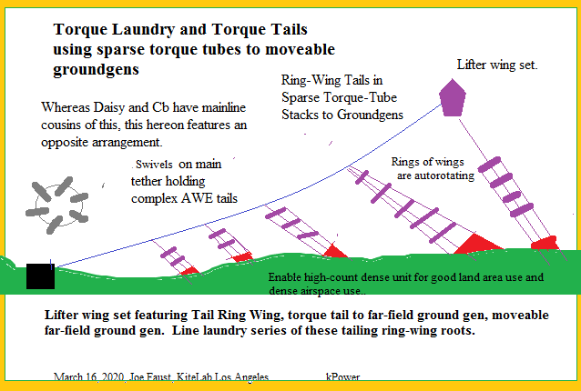
- Possibly movable groundgens
- Various adjustments of wind-direction changes
- Shown unit may be duplicated for farming or foresting.
- Option: no main-tether winching
Lifted Wing Set to Carry Series of Tails of Torque-Tubed Ringed Wings to GroundGens
New-Topic rationale: This is quite distinct from main-line slanted-and-held
torque-tube rungs of wing rings.
Hi Joe, The rotors you’re showing here are going to be very draggy for the lift line.
By keeping the rotor plane inline with the lift line the rotors develop their own lift and really only need steered by the lifter.
Also you are relying on the wind direction left to right.
That may be aleviated by having the whole set on a ground rail like this old sketch.
But even back then we could see the inclination of these trailing rotors was problematic
Thanks, Rod. The topology for one tail or very many tails from one lifter set will be kept in file for exploring along with your good progress on lift-assist rings of wings in open torque tube for one tether strand from lifter-wing set. Certainly, as implied in sketch and in your firm statement on the drag cost on main tether, the tails or roots drag on the main tether. Part of the aim in the sketch is to get many tails/root assemblies from one downwind lifted tether; each tail/root implies more lift from the lifter set. Work done increases with each tail/root.
Edit#1
Something to know, perhaps:
-
Take from Daisy the assembly from anchor to junction to lifter tether. Operate the assembly as regularly. That operation has a drag component, say D. Find the power curve.
-
Have an aside lifter tether matching the lifter tether of 1. scene, but add a segment of main tether to a fixed static anchor. Then attach the Daisy subassembly to the main tether of this aside system; attach the subassembly by swivel to the main tether at a point where a mid-far-field groundgen may be situated. Adjust the said swivel point so that flight operation has the Daisy subassembly taut; perhaps have an elastic rooting line from swivel to top of the Daisy subassembly. Adjust the wings on rings to operate for good autorotation in the new orientation (swivel to groundgen is now as per topic drawing in first post). Once the wings on rings are set and autoration occurs, find the drag on the main system tether. Find power curve. Something will be learned during the experiment.