After additional experiments about tilted rotors,I added some notes and a sketch of the Experiment Findings: Flexible kite carrying a turbine within a torus-shaped balloon (DOI: 10.13140/RG.2.2.29622.00320):
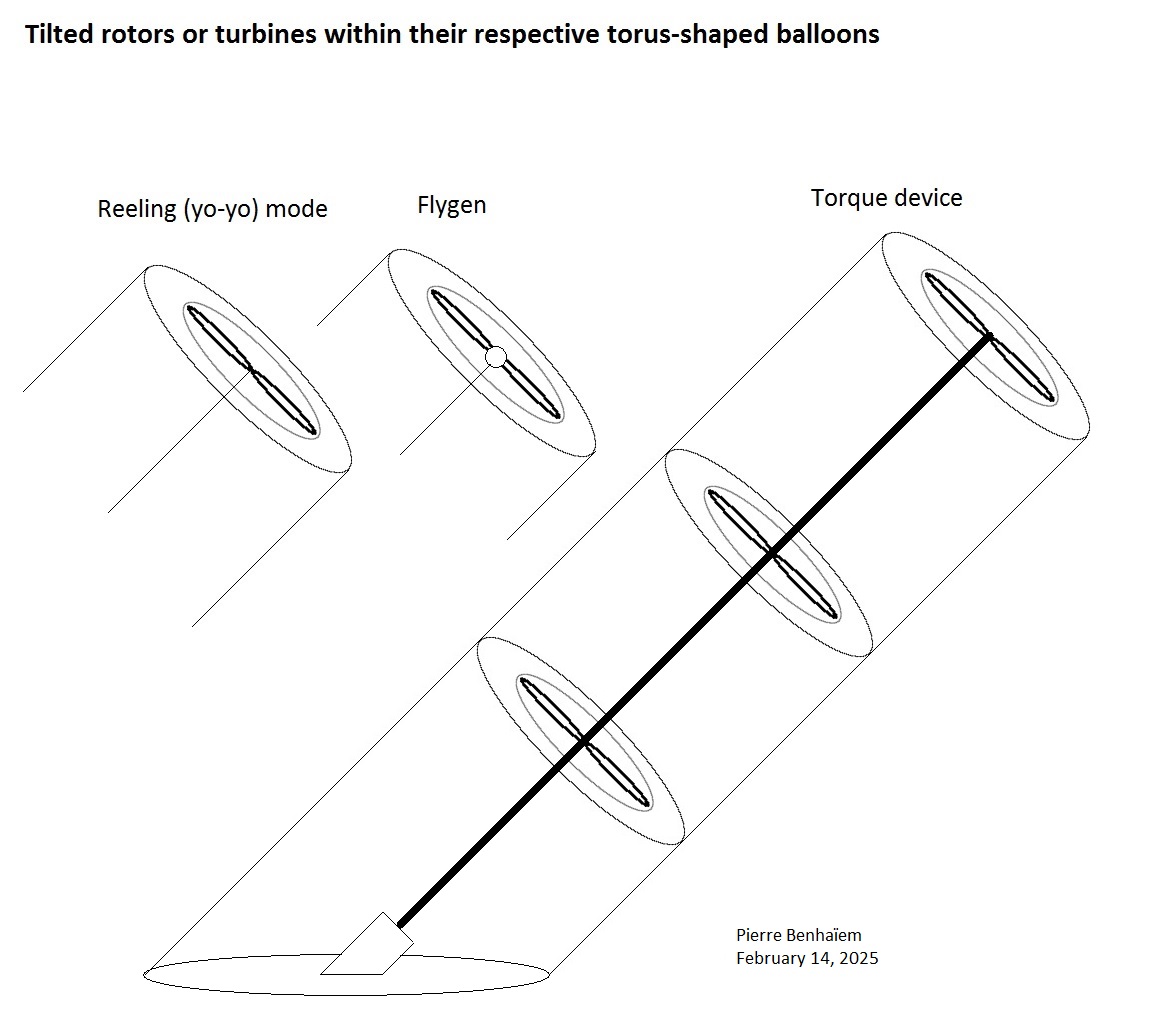
Tilted rotors or turbines within their respective torus-shaped balloons
Additional experiments with the same tire (inner tube) of 42 cm outer diameter and 24 cm inner diameter and the same 20 cm diameter propeller were performed, at low angle of attack of approximately 15 degrees, and high angle of attack of approximately 45 degrees. The propeller spun faster. But some other experiments with various wind speeds (see the § Anemometer inside the 42 cm diameter tire) showed a significant drop of the wind speed even for angles of attack above 45 degrees. Paradoxically at least in appearance, the propeller ended up rotating faster than alone, while receiving less wind power: this may be due to mechanical questions of stability of the axis.
This leads to thinking about other AWES, considering a very high angle of attack of about 50 or 60 degrees if possible, and a thinner torus the objective of which is not to increase efficiency but to mitigate the loss of efficiency. A thick torus is probably blocking the air.
Pull devices in reeling (yo-yo) mode with gyroplane-shaped blades providing both lift and power during the reel-out phase (the device moving away from the ground station by unwinding a winch operating the generator). These devices can be arranged in train of multiple units, some torus being inflated with helium in such a way that the global buoyancy is neutral.
Flying generators [7], or flygen: here a torus inflated with helium, blades and a generator per unit.
Torque devices including superimposed rotors and tensile rotary power transfer to the ground, as described on the Fig.89 and other figures [8] and tested [9]. But as these embodiments include peripheral tethers, they cannot be implemented because of the diametrical ropes of the torus which would prevent their rotation. This is why in the sketch following, Fig. 1 [8] with a single shaft is taken as a reference. Each rotor or the majority of rotors are surrounded by a torus, providing both an additional power and positive buoyancy allowing the train of rotors to achieve a theoretically unlimited length, mitigating or cancelling the catenary sag effect which is due to both length and weight, allowing scaling. Both torus and rotors are concentric, and tied by their common center.
The torus are fixed in all tilted or not tilted configurations. Only the rotors are rotating.
In all variants, the torus are also protections for turbines or rotors, and allow an arrangement in farms of unities in bumper car mode, where collisions are of minor effect.
Multiple units can also be easily achieved by implementing a rope-like links between the multiple torus, torus by torus. A similar arrangement with not tilted rotors was mentioned above.
Lifter kites can perhaps be added.
A sketch of the three main arrangements
I don’t know if kite lifters would really be necessary.
Concerning the torque devices (references to SuperTurbine ™ Serpentine, and Daisy), it is possible that the positive buoyancy with helium in the torus tends to position the rotors, stabilizing them in their inclination, according to the level of the buoyancy, and without requiring any additional lifter kite. But I am not sure of it.
Temporary conclusion
Torus-shaped balloons act like simple and efficient shrouds. They also work as supports and protections for the turbine inside, allowing higher density in a farm in bumper car mode where collisions are not important. They can be carried by static or crosswind flexible kites. In the configurations where the torus is tilted, the efficiency drops, so thinner torus should be implemented.