Combined to lightweight compression and tension members made of carbon fibre composites live load to dead load ratios of more than 300 can be reached under homogeneous distributed load.
Not sure where to put this so I’ll reply to myself…
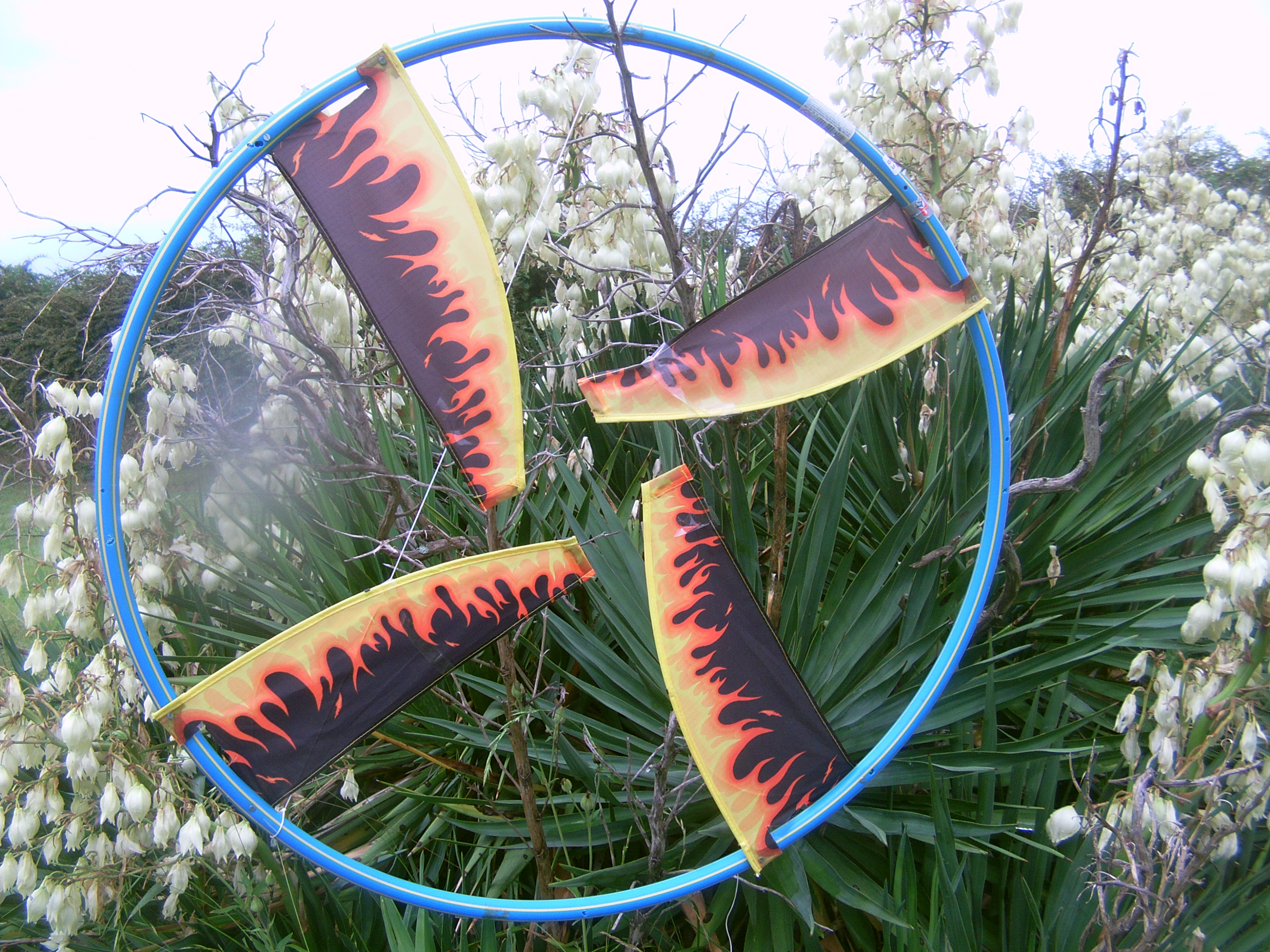
Tensairity Torus
I’ve been struggling to get this idea off the ground (pun intended) and (another pun) feel like I’m reinventing the wheel a bit here (given Roddy’s original daisy designs) but, for what they’re worth, here a few images and clips of where I’ve gotten to (and probably about as far as I’ll ever get!)
Creating or procuring inflatable tori of suitable dimensions isn’t easy…the solution I came up with was 2 litre sparkling water bottles (saved up over a year or two!) - dried and stuck in the freezer and then capped, which, assuming that the bottles were not significantly dented initially and a 30 - 35 deg temperature difference between the freezer and ambient air temperature when flying, might give a pressurisation of 1.1 bar. The bottles are held in position in sleeves made of sliced bottles. The compression elements are 20mm fairly stiff UPVC ducting pipe. In a true tensairity structure the pipe and bottle rings would have been have been uniformly bonded to one another, here they are attached intermittently, and the bottle ring is tensioned with strings looping along the ring. Originally I tried a 24 bottle ring but this wasn’t stiff enough: reducing to 18 bottles produced a reasonably strong ring of about 2 m diameter.
Wanting to stick with a inflatable transmission but running low on water bottles, I tried a milk container ladder, but they weren’t really up to the job, and I just ended up with a mess of tangled lines – see photos of triple torus on ground! Scaling back to a single turbine and using a 25 metre MDPE water pipe we at least managed to get airborne and spin round a bit (in an approx 20-25 km/hr breeze).
Obviously things are far from ideal in terms of aerofoil shape and the bicycle wheel attachment point was not spinning as freely as I’d hoped, and I’m not sure about any friction between the pipe and the kite line along it’s length – though I guess that if there was any major problem the kite would have gone fly about.
So…is there any point to this?? (Here commences a rant…so please disregard if you prefer.) The point does relate to some of the other concerns on the forum…the software vs hardware discussion and, more fundamentally, is there any future to AWE outside, perhaps, of some niche applications. I wonder what the debate would have looked like a century or so ago in relation to hydroelectricity had people had the same access to IT as we have today. I expect that the software enthusiasts would have been proposing a variety of ingenious fishlike devices packed with semiconductors weaving through fast flowing streams, reeling out yoyo lines or sending back electricity (in rather limited quantities) along their tethers. For better or worse, our predecessors, not blessed with microchips (or any electronics to speak of) resorted to the hardware approach, and a pretty extreme hardware approach at that, involving tens of thousands of tons of earth and concrete and some pretty unintelligent, slowly spinning turbines. (I’m not getting into a debate about the virtues/vices of hydroelectricity…but one does need to bear in mind that the lost habitats and displaced people have to be set against either the lack of electricity or the increased fossil fuel combustion which would have resulted had the rivers not been dammed.)
If one were to sum up the philosophy behind hydropower in a couple of words: massive and passive come to mind. Their applicability to the Hoover Dam or the Three Gorges is pretty self-evident, but the situation isn’t that dissimilar to any of the other proven forms of power generation, be it solar arrays, tidal barrages or conventional wind turbines (as well as nuclear and fossil fuel). Of course, all these forms of power generation are now monitored, controlled and integrated electronically, but none involve IT as an intrinsic part of the energy conversion process – they were all conceived of and in most cases implemented (at least initially) in a non-computerised world.
So is AWE a completely different beast? I’ve no pretensions to prophecy, nor to expertise, but it seems to me unlikely that, if it is to become a significant part of electricity production, it can avoid going down the same route. “Massive” may not seem the right word to apply to airborne structures – “bulky” might be better, but the idea is the same: in order to harness significant quantities of power above the reach of conventional wind turbines one will need to have large objects aloft (even allowing for as low a turbine solidity and as high a concentration at the blade tips as conceivable.) I’m also pretty skeptical about relying on active controls for safety critical functions – that may be OK for high performance aircraft (which, of course, are what Makani and others have been designing) but not for large scale AWE. In a very uncertain world, power regulation and overwind protection need to be as passive as possible – turbines and other airborne components need to deform or reorientate themselves to survive weather extremes and to be sited far away enough from population centres to mitigate the fallout from catastrophic failure.
Arrays: to array or not to array…is that the question? Again my own (limited) experience of tangled kitelines makes me a bit queasy when it comes to having lots of AWE components flying about in close proximity (and especially if one is relying on software to keep them out of each others way.) More fundamentally, one needs to consider where one is siting the installations. While the prairies of North America, the Siberian tundra, the Sahara or the Australian outback could host large arrays well removed from population centres, in the case of Europe and other densely populated regions one really needs to be focussing on what works offshore. Offshore, the case for single large structures over multiple smaller ones is compelling, and becomes ever more so the further out and deeper one goes.
…So how does this relate to a 2 metre water bottle torus? The principal question is obviously one of scalability. The key advantage of a torus as the backbone of the architecture is that it frees the blades from a structural role – ie. vis-a-vis a conventional HAWT where the blades are mainly there to support the blade ends – so that the blades can be optimised aerodynamically (and for longevity or any other relevant considerations). As far as the mass/swept area ratio and whatever unfavourable cube-square law it follows, this could be overcome (at least in part) by using a bit of the electricity generated to heat the torus or, heaven forbid and the Hindenburg not withstanding, filling it with hydrogen!..but perhaps not so outlandlish for tori tens of kilometres off the coast and flying at over 1000m, widely separated and protected as far as possible from lightning strikes and terrorist attacks.
Anyway…enough of my fantasy/rant…I agree in principal with the advice to start small and scale up gradually, but I think I’ve reached the limit of what I can do with improvised materials in my loft. If anyone thinks it worthwhile to obtain/manufacture a better torus – and to improve the transmission system (either Daisy fashion with scaled-down tori or some other way) I’d be interested – and would wish them luck!
Nice effort @philip
Especially appreciate the recycling
Took a lot of dedication to sparkling water to get all that building material.
One day I am going to save egg cartons for an anechoic / sound proof room
Having the blades on the inside - they will be less likely to tangle than mine.
Interested to know what results you got from the various drive shafts
The thin one looks like it would have less drag aligned in both torque and downwind
Thanks Tallakt - very kind of you…and thanks everyone for feedback. Ideally I’d like to pursue things - smooth out the transmission and attach a generator - but I’m pretty much at the limit of what I can do single-handed working at home and carting stuff out to the nearby field (which, given surrounding woods and obstructions, only works with a moderate westerly wind) on my bicycle. I do wonder what the optimum torus dimensions might be - and how these might alter as one scales up - and the trade-off between the volume and inflation pressure.
I think the inflatable torus can’t scale a lot. Even taking into account a relatively low tip speed ratio (2 or 3) the drag and also the mass are too high. I was able to observe quite a large drag with relatively thinner rings like the ones in the photos. And it looks like the rotor rotates slowly on the videos on the link.
If we look closely at the video below we can see that the inflatable wind turbine is real … until the moment it starts to spin (around 2:40).
Another video:
Only rendering.
A Tensairity ™ ring would be thinner and generate less drag. But you have to control the pressure, and the mass would end up being prohibitive as well as the drag.
Another way is dividing the blades which are settled on spokes, using a rigid torus in rim drive configuration like on Blade Advantages - BarberWind Turbines . But this would be still too heavy for an AWES.
To learn more about that you could make (straight) tensairity beams of different dimensions and do load bearing tests, just like Rolf Luchsinger did, or maybe just ask him. I think that’s an interesting question too.
The novel idea you have here is the torus, I would focus on just improving that and not worry too much about the transmission or generators. You could always just put it on a pole and use a flywheel instead of a generator.
Thanks for comments/advice…I agree that concentrating on the torus is the most “useful” thing that I (or someone else) could do - though I note the views that from the point of view of weight and drag the torus might be a non-starter. (I hadn’t realised that the Winflex design never really got going). Well, I’ll see if there’s any more I can do…
It seems at smaller scale something like the inflatable SUP design could work to make a relatively lightweight torus with foil sections. The ideal shape will not be a ring but a regular n-gon.
With high elevation angles though that plan is less interesting because the wing section will stall for some regions.
So the next step would probably be to reduce the surface area facing the wind, which would lead towards high pressure inflated structures or something based around carbon rods.
@Rodread I believe advised against inflatable rings though. He would be a top expert on the subject, Im sure he would be willing to share his experiences on this.
I had terrible experiences trying with inflated torus kite turbines
@tallakt is correct
A network kite turbine using multiple units of the Bruno high pressure kite as blades makes a lot of sense for handling and scaling
Handling especially,… with bridling going right out to the tip, there’s virtually no chance to snag a tip inside the tethers… Very handy
That advantage means concentric rotor layering of blades in the turbine will also be easier to handle.
How robust, efficient and easy it is to manufacture vs a small “rigid” extruded/expanded foam wing?
I don’t know
I’m going to give something along these lines a trial first though as it’s what I know for now.
Both the powered rotor and transmission are better as n element polygons
The polygons were initially trickier to implement on the rotor as the round section tubes I used allowed twist in their connection into the fuselages thus the whole rotor could collapse. Doh.
Also in the unfortunate case of a blade ground strike there is a much greater chance of snapping a tube with n polygon.
Will be using polygons with better tube and connection profiling this time.
&yes
I’d like to see an experiment with arrangements of high pressure kites as the blades in a kite turbine and potentially blending into a similar tech for the more rigid parts between the blades.
Which maybe takes us back to the topic
Tensarity beams
IIRC that’s because your ring is quite floppy and the pull of the blades and tethers pulls them into that shape anyway. If you wanted to make a bigger ring you wouldn’t want to make it as floppy, so then I think a ring would make more sense, as you can more easily make that more rigid, if you construct it like a bicycle wheel for example. Also as this topic is about tensairity tori, it makes more sense to make those with a continuous curvature so you don’t have bends in the rigid elements.
I’m also guessing a polygon will have more drag than a torus as it will perturb more air. I wonder what difference that would make.
What’s that? Oh, drop-stitch inflatable stand up paddle boards.
Yes, its the same argument as back then. If you have a discrete number of tethers, then the rings are better implemented as n-gons with straight rods between the tether attachment points. In this way compression is served by a straight rod rather than a curved segment. This is just an observation, not backed by experiments
@windy hope this reply is OK here & we’re not drifting from tensarity torus…
Yes - a pre-formed ring makes more sense than a ring formed from a straight elements bent into a ring.
However a single thin outer rim design will not hold stiff even with radial spoke tethering.
A lattice form may improve rigidity but as you noticed - increase drag - and I’d agree
On a kite turbine as per my practice…
a 3 blade rotor ring takes a rounded triangular form in operation.
So there seems little difference in working form
The basics…
Tethers are in tension - Tethers coned onto a ring/polygon compress it with a function the tension and how steep the cone is.
During torque transmission, tethers between rings/polygons take a hyperboloid shape (~2 cones) the cone shape compresses the rotor and transmission rings/polygons.
Polygons resist the compression better than rings - polygon material is inline with the compression between connection nodes. Rings of bent material are weaker as they are already holding stress before loading. Rings however hold their planar shape well as they are formed from 1 piece. Polygon beam elements need to be fixed to their nodes and/or held to the center to avoid twisting the polygon plane.
The main rotor is floppy ~ a long length of thin stiff material flops. This flop will be accentuated by an element which tends to twist a node out of the plane (such as a blade around a node might)
A blade fuselage with it’s tube formed over a small radius ring will be sprung more forcefully into planar alignment than a fuselage on a larger radius. (the amount of arc of contact is important)
A blade fuselage formed over a polygon can be fixed to the polygon beam to avoid flop.
It all sounds bad for rigidity scaling until you add
A top cone to start separating the lifting line before the rotors.
Bridling to keep the blades in alignment as they lift
Bridling to bank the blades so they expand the rotors
Enough tension to keep the transmission from excessive coning
More transmission lines to share the loads (also = more blades per rotor)
Closer rings/polygons per radius to ease the load
Active scaling in tension
Lattice form beams
Custom form beams
and more
the torus is peripheral (Winflex example, with a thick inflatable torus) or if
the torus is the root from which the blades start (Daisy example, with a thin internal torus).
For 1) the drag will be maximum because the torus is placed at the fastest part of the rotor.
For 2) the drag will be much less, and can be compensated by the distance of the blades from each other, being the torus diameter, and therefore their higher velocity on all their respective areas (velocity remaining lower at the base, but higher than for attached blades) resulting in a larger swept area.
In my opinion polygon shape could perhaps be suitable for 2).