For what I believe drag comes from the axial flow, and lift is perpendicular to the flow. In crosswind flight the high power is generated by the lift that is perpendicular to the apparent wind as for a blade of a wind turbine, but roughly axial in regard to the real wind during the reel-out phase in yoyo mode.
Drag-based wind turbines such as Savonius as expected to have a power limit of about 4/27: the same for yoyo AWES which could be seen as a lift device in regard to the crosswind flight component, but also a drag device by considering the whole swept area which goes downwind as for Savonius, so roughly in the axis of the real flow.
In AWE lift (yoyo) and drag (flygen) devices have the same efficiency in regard to the wing area, but not in regard to the swept area. However current AWES use a tiny part of the wind within the swept area, so this difference is not really a concern, until we want to maximize the swept area to limit the space use.
We could deduce it could be similar for current drag-based and lift-based wind turbines. There is some study about the ratio TSR/power of Savonius turbine. Unusually high TSR are considered:
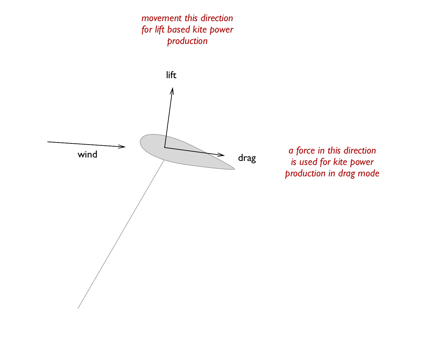
@tallakt’s sketch makes sense as the forces are considered in regard to the wing.
Another possibility is to consider the forces in regard to the working of the whole.
Some comparison between a drag-based wind turbine such as a Savonius rotor and the AWE yoyo mode could also be considered as both generations go downwind.
Tallaks footnote: ***(note: wind is apparent/effective wind: (wind relative to ground) + (velocity of kite))
The reason that we get improved performance with crosswind action is because the effective wind velocity increases. The effective wind velocity is the vector sum of the wind speed and the movement of the turbine (or kite). For example if the wind speed is 10 m/sec and the turbine is moved laterally at 10 m/sec, then the effective wind velocity is 14.2 m/sec at an angle of 45%. In this condition, cosine losses are significant so we must reorient the turbine to face the effective wind velocity direction. This is difficult to do with the Superturbine® or Daisy designs. Perhaps my multiple turbine design with double universal joints will be more successful.
I attach a @gordon_sp’s paper (that I took from the old Yahoo forum) about this turbine design with double universal joints, thinking it can be interesting when the apparent and effective wind velocities are roughly equivalent. The implementation looks difficult. TETHERED TURBINE ORIENTATION.pdf (99.8 KB)
When the apparent wind velocity is far higher (as for Makani’s wing or FlygenKite) the turbine is permanently oriented face to the apparent wind.
Some observation: the blades of SuperTurbine ™ or Daisy can be seen as moving crosswind. The hollow section of Daisy allows the full blades to go faster and sweeping more, makes Daisy to be an intermediate between a rotary kite with a rotor and a root like SuperTurbine ™ or Sky Windpower, and a crosswing kite like Makani’s wing.
I can be wrong because of some embodiments from @dougselsam’s US2002192068 (A1) serpentine Wind Turbine patent.
As an example the figure 88 represents a SuperTurbine ™ without central shaft, the description mentioning a torque transmission lashing (18). This version can be seen as a TRPT.
Doug highlights the advantages of high rotary speed for motor generation and has a brilliant set of designs… As such, Doug prefers to keep rotor surfaces close to the axis. I’ve been trying to do away with a physical component to the axis, focussing more on wider sweep radius.
That is the problem. “I just looked…” : we must take the time to think first. An analysis of a patent is not looking at an image.
This patent, like almost patents, contains an independent claim followed by dependent claims.
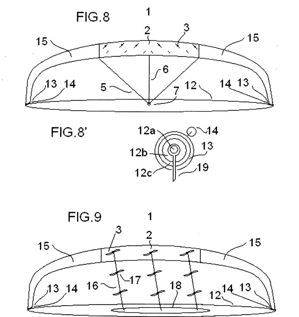
The independent claim is about the integration of turbines in a sail within a same plane. The claim 9 works with the figure 9, and is a dependent claim that is connected to the independent claim 1.
The figure 9 represents a device where the first turbine is integrated in the kite, unlike the device of which you provide the video. A picture is not enough, not even the essential: reading the text. The figure 8 represents turbines integrated in the kite, as for claim 1 and other claims, unlike the device on your video, a time again.
Pictures and concepts are not the same. Patents are about concepts.
I precise also it was a French patent, written in French language.
However there are elements I quoted in this patent, concerning a prior art from you, from Dave Santos, and also from @dougselsam, not in regard to the embodiment 1, but in regard to the embodiment 3, concerning the implementation of an arch and the ground installation. I provide the Google translation (with some mistakes) from French language of the concerned extract below from the link you provided:
" According to a third preferred embodiment for the massive exploitation of high winds and high altitude, the assembly (1) is part of a type of arch kite (1, 15), forming its summit, strings (5, 6) are fixed to the pivot (7) located in the middle of the area defined by a circular rail (12) allowing the orientation of the arch (1, 15) according to wind direction 25 and drawn and designed by Roderick Read the association “KitePower”. Dave Santos at “KiteLab” and the association “KitePower” student airborne energy systems, described and performed under the name of “Mothra” power arches enabling high stability and high lift capacity and capable be carried out at all levels, constituting a breakthrough in basic architecture of airborne wind turbine 30 as having the potential of a wind farm on rounds, with one set of great lightness. Both ends of the arch are attached to the circular rail (12) .Chacune the ends of the arch (1, 15) is attached to a winch (14) provided by the applicant, each winch (14) being attached to a shoe (13) recessed downwards and thus sliding away from supports (19) 35 the two winches (14) wind and unwind the two respective ends of the arch, particularly during take-off and return operations in order to clarification of the operating zone, the turbine (3) taking off as a helicopter as 3,025,006 for other 5 embodiments, their generators working as an electric motor. The electricity is routed by the strings (5 and 6) _ as for other embodiments or (16) or by legs (15) of the arche.Les strings (5, 6) can also be deleted when the assembly (1) is integrated to the arch (1, 15)."
This patent is also available on Espacenet - Données bibliographiques.
Below is a video summarizing this patent. It begins with a kite comprising an integrated turbine, as for the embodiment 1, and finishes with an arch as embodiment 3. You can also read the text mentioning Dave Santos’ contribution.
So, your…
…only proves that you have not read this patent and particularly the extract I quote above.
Moreover as you mention it is not more a valid patent. So …
…So this remark is misplaced, a time again, and is also a nonsense, since there is no more right connected to this patent. I have other withdrawn patents: I guess you are interested by them today.
I don’t believe you are suddenly interested in my old or recent patents for pure intentions. Are you embarrassed by the questions I ask (without serious reply from you) about your system as on Network Kites and Daisy network kite rotors - #37 by PierreB?
In the other hand Doug’s US6616402 is a valid patent. Doug built central shaft versions of Serpentine, but also conceived a TRPT WIDE version of SuperTurbine ™, without central shaft. See the figure 88 below.
What you call as Daisy is SuperTurbine ™ from a valid patent. You claim Daisy is the first hollow stacked ring kites. In fact I saw some transverse thin rods between the blades. On the drawing above the rods are thicker: it is a tiny difference as there is also spacing between these blades.
But be quiet: Doug will not ask you some royalties. Generally patents prevent business, but not building for experiments. And I guess Doug is rather happy you build his TRPT SuperTurbine ™ version.
By the same in a similar way as everyone filling patents I can be inspired by previous concepts, trying (sometimes with success for the novelty, sometimes no due to the huge prior art I don’t know, leading to the value of the patent search report) to make something new and workable from what is known.
And also: nobody has still find a workable design-concept at utility scale. I think a successful design can be something similar to known designs, with a tinier difference than that between the devices on your 2012 arch video and on my figure 9, although a higher difference than that between what you call Daisy and the TRPT SuperTurbine ™ fig. 88 version.
Hi @PierreB I’m going to assume you’ve done editing that post now @ edit 13
The difference between Doug’s Superturbines and Daisy. - Radial material to hold the blades to the root. Daisy can and has run in tension, expanding the ring radially without any material going radially to the axis. Also - Networking where it’s wanted too. That alright with you @dougselsam?
Daisy has admittedly mostly run with tensile lines to root rings which go over and around a lift line. They’re not necessary.
One interesting thing that popped up: @Rodread, did you consider using «star» spacers rather than rings, like @dougselsam does in his patent? The length would be slightly longer for the spars, but I believe the compressive force would be a lot less compared to that of a ring. One of the methods should yield the lowest weight.
Not sure what you mean by spacers here @tallakt
Is it the part between driving kites on the same rotor level?
I’ve been analysing both rod and ring and also concentric ring configurations for that.
To help clarify confusion shown here in regard to where ideas originate and differences between my Daisy class designs, and @dougselsam’s US6616402
In reference to Fig 30 in Doug’s patent, US6616402, it has lines between tips, is that what you mean @tallakt by ring? (significant differences with fig 30 are tips inside the tensile lines and blades solidly connected to the root, also blades flat to rotor axis plane without banking.) Fig 31 - no tip connectors and tips outside on a rigid hollow axis frame. (Yes, hollow axis, but very solid therefore very small in scale)
Also fig 48 a tube connects the rotors at the root without an axial line. fig 50 Rigid outers and TRPT inner. Fig 83 also has a rudimentary TRPT network. YES Just as I’ve said all along @dougselsam US6616402 existed before my work on TRPT (Not my term) and Networked kites (Also not my term)
Relating back to the Original post question … Is Doug’s US6616402 The most crosswind kitepower system because it stays close to the axis? Probably depends how aligned that axis is with the wind.
I am not to bothered with the patent discussion. But this is of interest to me. I hope the figure explains what I meant by ring vs star… I am also not too bothered by where the kites are placed. I gather you could have any length of torsional transfer, and the only penalty being mass, drag and torsional dynamics. Once you start adding kites, it gets trickier because you want the tether to become increasingly thinner. Anyways, I was just wondering about star vs ring…
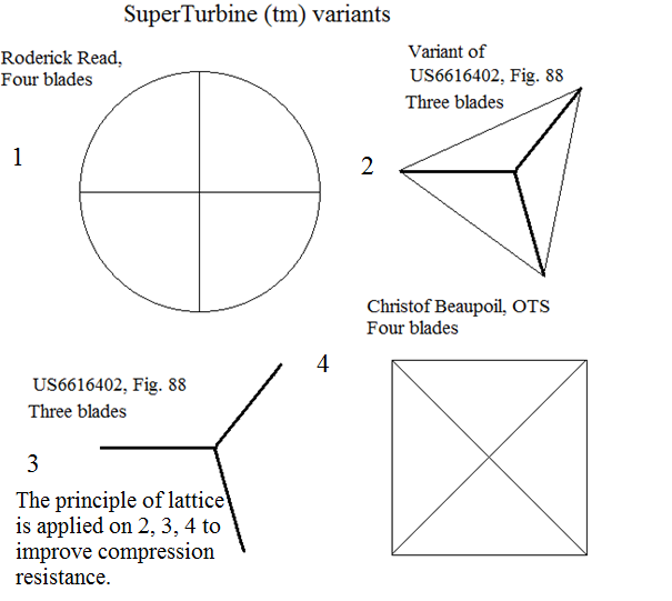
“Daisy” IS a SuperTurbine ™. In the “hollow” there are two diametrical and perpendicular rods, so the “hollow” is not really hollow. Below is a @Rodread’s photo of SuperTurbine ™ showing the ring AND these spars. In @dougselsam’s patent, figure 88, there are only spars which benefit from lattice effect with not right angles favoring the resistance to the compression. I put some sketch still below with different configurations.
I precise @someAWE_cb’s is not still a SuperTurbine ™ as it has only one rotor. I put it in this sketch to show what are used means in regard to compression concern.
Nice clear description thanks @tallakt.
I use the ring topology mostly, sometimes polygonal with node cuffs, Where Dougs patent depicts the star mostly. Sorry to mention patents but @PierreB seems to be losing his cool over the issue.
The ring topology isn’t in Dougs patent other than as a part of a rigid latticework in fig 64. You can tell it’s rigid as the word strut is used in the description. (1st year in the secondary school where I teach)
As for the implications on torsional transfer limits… I started a new analysis series this morning. I’m hoping to publish results on scaling soon. Busy assisting with base station development today though.
Pierre, you are wrong. Get this right.
fig 63 and 64 in dougs patent show latticework, it is rigid spar latticework.
What you see in my photo of a Daisy system is a tie. A tensile member.
Figure 88 has no latticework. yet it does have spars, rigid members leading to the axis, which do help superturbine resist compression from the torsion demonstrated on the tethering lines.
You may care, for a change, to pay attention to the bank angle effect on the rotor and torque transfer dynamic.
I’m glad to have been shown, that my summation argument in my initial post, (daisy being the most crosswind kite power system) is probably wrong.
Please keep cool @Rodread. Ties or rods, the hollow is not hollow. I speak about lattice effect or lattice principle about fig. 88, not latticework as such. Latticework uses triangular elements. The 3 blades from the fig. 88 are connected by three rods forming three angles allowing to resist compression better than the ring, even as the first purpose is only the connection of the blades. The ring you use is your personal contribution and I congratulate you for it. However I doubt it will be sufficient as the system scales. And internal ties prevent deformations only around the axis as you know. Bank angle effect has been discussed numerous times and is a possibility, the price (for now as some improvement could be done) being a lack of structural rigidity making the system to be vulnerable to wind changes in intensity and direction. And structural rigidity implies more rigid elements in flight, leading to more weight penalty as the system scales.
I repeat … Our definition of ‘crosswind’ is the movement of the whole device across the wind window and not the circular rotation of a turbine blade. Kitewinder does not operate crosswind unless the lifter kite moves across the wind window and drags the turbine with it.