Toward the worst AWES

I don’t really understand what’s happening there. That system looks similar in some way to what you want to do. It has a rotor that is relatively free to pivot, just like in your system. The rotor then pivots up in the wind. Do all rotors do that when free to pivot or is there some other reason it pivots up, like the pivot point being some distance below the rotor or the wind pushing against the tail of the airplane?

Autogyro rotors are free to pivot I think and they also seem to pivot up.

I wrongly thought this device (on the video) was what you wanted, as you mentioned a hinge. But now after seeing your sketch I understand better what is your purpose.

Nor is it similar to what I want, as I describe rotors spinning around a rope while the device on the video, or a gyrokite, or an autogyro, all have a fuselage, a rudder, a stabilizer, and an axis for the rotor, said axis being not the main line.

This is the similarity. Because your tube is very short, the rotor can pivot relatively freely if the line tension isn’t very high. The longer your tube, the less the rotor is able to pivot.

  1. In a side there is a more or less long tube or rod along the line and a rotor around.

  2. In the other side there is a complete gyrokite.

Both are quite different structurally and work differently. There is no similarity. The variation in the length of an element (tube or rod), even with supposed consequences, should not be confused with a structure.

In 1. the rotor is more or less maintained by line tension, while in 2. the rotor depends on the gyrokite which is held by the main line without any requirement for a rod, as a gyrokite flies like a kite.

Hi Pierre: Thanks for providing a link to one of the videos from my Youtube channel.
I realized for an audience here of people who don’t really know much of anything about wind energy, I should explain what is shown in that video: Overspeed protection. As I like to say, in wind energy, overspeed protection is not the main thing, it’s the only thing. Since the power in the wind is a cubic function of the windspeed, strong winds will generally burn out a generator or destroy the turbine in some way. The max windspeed most turbines like to see is about 28-32 mph. Much more than that, and your happy generator will become unhappily hot. This is a result of the wires of the generator windings carrying too much current. Once the heating of these wires starts, there is a cascade effect: it gets much worse very quickly because the resistance of a hot wire increases with temperature, which makes the wire hotter still, until the insulation burns off and sometimes the wires melt. So a turbine must have a way to dump extra power over whatever max continuous windspeed it is designed for, or you’ll burn out your generator, and/or destroy the turbine in some other way. To disconnect the turbine still aimed direclty into the wind might work sometimes, for a strong enough turbine, but in general, things start to fly apart in very strong winds, and unloaded blades can even go supersonic, at which point you do NOT want to be anywhere nearby when they fly loose at that speed. You’ve seen pictures of 2x4 lumber penetrating a palm tree trunk in a hurricane? Well wind turbine blades can do the same thing. I’ve seen a photo of a little plastic blade that penetrated a roof, for example. A wind energy system without overspeed protection is like a truck without brakes - maybe OK for a demo in the middle of nowhere, but very bad for a populated area. Any turbine without overspeed protection will destroy itself at some point. The video shows an interesting configuration for overspeed control, but the gravity-tail sideways furling method developed in the 1860’s for water-pumping windmills is still the method used most for small wind turbines up to around 10+ kW, even today. The reason is it uses the already-existing yaw bearing as overspeed protection and only needs to lift the tail rather than the whole turbine. There used to be a lot of really smart people in this world. Not sure what happened…

1 Like

Some experiments with a tiny 0.2 m² pilot kite with three 0.555 m diameter rotors coming from three gyrokites and sweeping a disc of 0.241 m² each. I think a use for yoyo mode would be difficult due to the requirement of starting rotors.

However, the assembly could maybe provide a complement of thrust at high altitude by using many rigid elements with a long service life and could perhaps be usable for scaling a pilot kite for Daisy rotors. But this system of lift can have some limits: on the second part on the video the rotor 1 (which is closer to the kite) and the rotor 2 pull very strong. As a result the elevation angle is lesser until the rotor 1. So stacked complete gyrokites could allow to maintain the elevation angle, while rotors alone could not, or would require a larger pilot kite.

Rotors (and also the pilot kite) with a higher L/D ratio would be desirable. For now the elevation angle is only about 45 degrees for the pilot kite, and from about 20 degrees for the two rotors at full rotation speed due to their disc drag, to 30-35 degrees at lower rotation speed or without rotation, mainly due to their (low, 40 grams per rotor) weight. Some more precise measures would be useful. The elevation angle of this gyrokite is about 35 degrees.

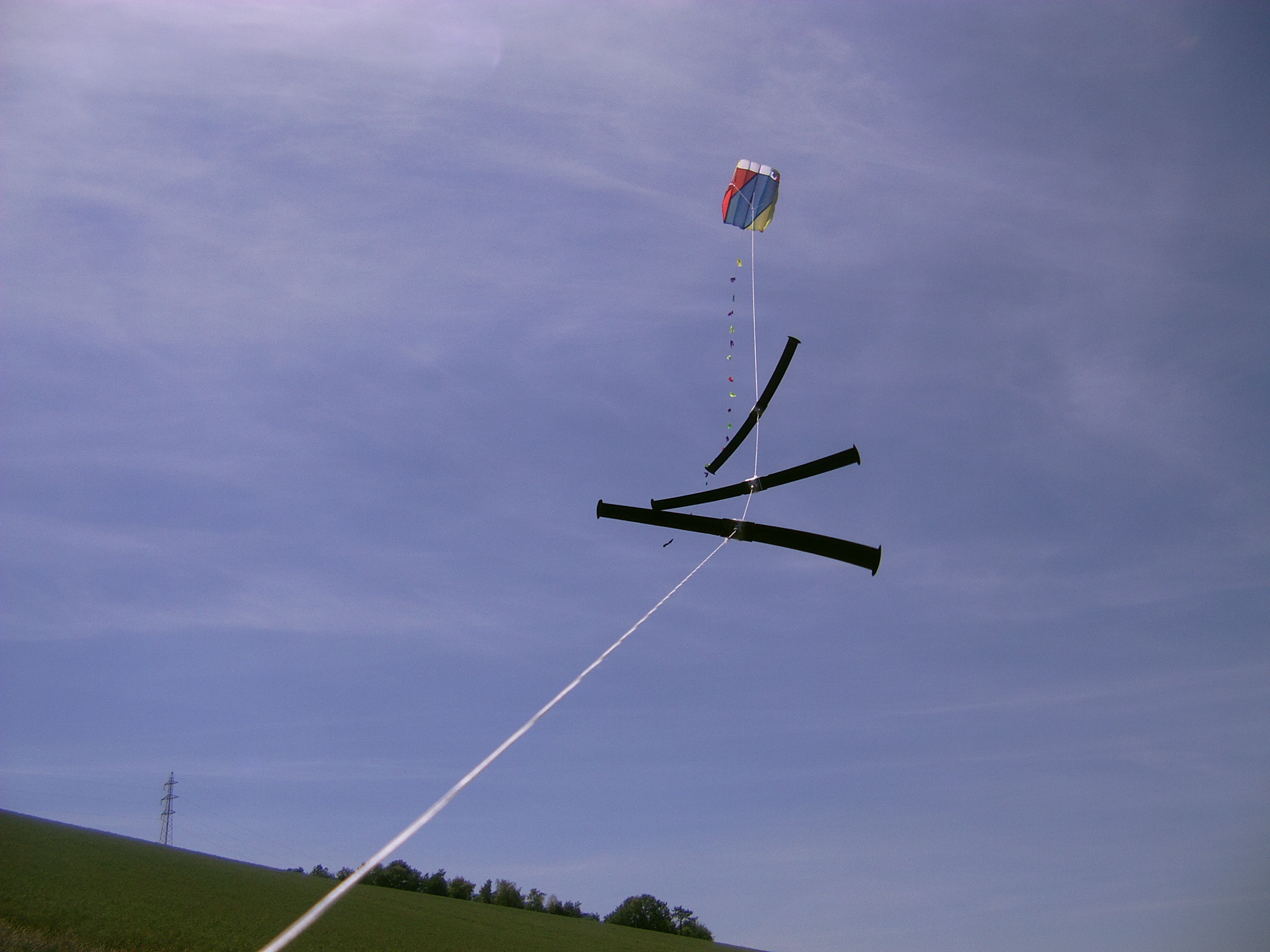
On the photo below, the rotors don’t rotate.

1 Like

The objective of the tests above and other tests today was to see if a small kite of 0.2 m² flying at a low elevation angle (about 45 degrees) could supply an elevation angle comparable to that of a gyrokite (35 degrees) to a multitude of rotors (from gyrokites and covering 0.241 m² each) rotating around the line.

Indeed, once tilted, each of the rotors produces its own lift.

But a steady flight state at high elevation angle (here about 35 degrees) would quickly be broken with variations in wind speed and direction and some other causes.

In practice, I was able to maintain the flight of a rotor rotating at full speed at a constant elevation angle of about 35 degrees for a while, but not two rotors rotating at full speed which stabilized at a very low angle.

1 Like

The rotor rotating around a rope or around a rod like on the photo below works like a bol kite with equal suspension lines in such a way that the bol kite generates only drag, like a windsock. When I held the rod by the basis by tilting the rod and the rotor, the wind force tended to put the rotor (rotating fast) in an horizontal plan, as for a windsock. But when I let go of the rod, the rotor with its rod was flying downwind a few meters height, unlike what a windsock or a bol kite would do.

This comment is difficult to understand without a schematic.

Do you mean if you span a (untensioned) horizontal line and to that attach the (horizontal) rod, the orientation of the rotor doesn’t change from its original (horizontal axis) orientation?

Do you mean if you use your hand as a pivot point for the rod, and the other end of the rod (not) supported, the rotor only pulls in the direction of the wind?

I can’t parse this.

I held and tilted the rotor rotating around a rod like on the photo below, the wind coming from back:

The wind speed was about 5 m/s.

  1. When I let go of the set, the rotor flew a few meters high for a few seconds downwind thanks to its lift.

  2. But when I held and tilted the rotor for a while, the wind pushed the rotor in its direction, the rod pivoting between my thumb and my index finger to become appreciably horizontal as on the photo below, said rotor thus losing its lift.

Yes (see just above).

A windsock or a bol kite are also pushed in wind direction, without providing lift.

There is a curve down in the rod. Maybe between 10 and 20 degrees? So that would point the lift of the rotor more down than perpendicular to the rod, gradually lowering the angle of the rod. There’s also gravity.

The idea of using a rod and a bend in the rod, is that you can point the the rotor in every direction you want, independent of line angle.

There’s different ways you could test in which direction the lift goes with different rotor inclinations, and how strongly it pulls. I think I’d go with something like the below video. Instead of the pulley being at the top, it would be at the bottom with the weight hanging below it and the rotor pulling the weight up. The taut tether would be your hypotenuse – which your rod travels up and down on – , you would change the angle of that.

My assumption is that when the hypotenuse is flat, the most work can be done. But you want a higher inclination than that so you can raise the inclination and see if you can find an optimum, or where it breaks down.

I think then you’ve found an optimum rotor inclination relative to the horizontal. I guess the line angle has to be a little lower than that, because other than lift you also have drag and gravity which you have to counteract?

On my last experiments I tried to see if numerous rotors can fly under a small lifter kite. Indeed each rotor should generate its own lift once it is tilted. But the answer to my question would be negative with the tested rotor because of its low L/D ratio (once tilted in an optimal way as for the gyrokite) of about 0.7 :1 (elevation angle = 35 degrees as for the gyrokite of which the drag of the fuselage can be neglected as it is very low): so this (0.555 m diameter) rotor generates more drag than lift. In my previous experiments the 0.2 m² lifter kite allowed to implement only one rotor rotating at full speed by keeping a correct elevation angle compared to its potential.

As shown on the video below the wind tends to push the rotor in its direction even when it is tilted beforehand, this force being little overcome by the lift of this rotor which is relatively low. See also the short flight in the end of the video when the rod was kept tilted before releasing it:

The rotor being motionless on the concerned photo, the curvature is only due to gravity.

But on the photo below, the curvature is mainly due to the wind force on the tilted rotor which generates more drag than lift.

So I see three possibilities to fly a tethered tilted rotor:

  1. Passive control, using a large enough lifter kite.

  2. Passive control, using a gyrokite.

  3. Active control: Makani-like for one-bladed rotor, or Y configuration (dancing kites) and some other possibilities.

An efficient autogyro rotor could have a L/D ratio of 4 :1 and more, which would lead to a greater potential for the whole area swept by ​​the rotors compared to the area of the lifter kite.

Concerning “using a rod and a bend in the rod”, the wind force will push the rotor in its direction as for a rod without bend. For this configuration a large enough lifter kite (1) would be required, as for a straight rod within the line.

Your experiments are useful.

To offset the rotor angle to the line angle you would need, I think

  • A high enough line tension (above and below the rotor) (which is a given since here we are talking about a yoyo system)
  • Enough rod length below and above the rotor so that the moment from the wind pushing on the rotor does not overcome the moment from the line tension.

So that would have it pulling at roughly 18 degrees. You could try to experiment, for example with the setup I described above, if you can get it to pull more upwards than that with different rotor angles. That should be possible otherwise autogyros wouldn’t be a thing I think.

Now this is a related topic: Bryan Roberts' Gyromill (Sky WindPower) the line tension and the rod replace the tethered autogyro. The question of interest is, have they found a rotor inclination that works for them?

1 Like

Indeed we are talking about a yoyo system. So the force (lift and drag) of the rotors is used, as for:
http://cdn.pes.eu.com/assets/misc_new/peswindissue17talkingpointskylimitpdf-891355291894.pdf
Unlike the previous system Sky WindPower rotor system is connected to a generator aloft that also assures VTOL.

Indeed, so on my previous comment I corrected the values that are rather L/D of 0.7, leading to an elevation angle of about 35 degrees, which is the elevation angle of the gyrokite from where the rotor comes. I don’t think a higher angle would be possible. Even this angle was difficult to achieve when I used the gyrokite by several wind speeds. Certainly a rotor of a gyro glider could have a better elevation angle by higher wind.

I put a sketch of trains of perpendicular rotors (as I use now), gyrokites, and rotors on their respectives rods with bends. For the last I don’t know if the sketch is correct.

For now I think the simplest way to obtain the desired angle of attack of rotors is by using the segment of the line with an appropriate tilting. The problem I see with rods with bends is the thrust adjustment which cancels the change of angle of attack. But I could be wrong. Perhaps also the bend rod system can be useful between the lifter kite and the first rotor, allowing to lower the angle of attack of said rotor thanks to the elevation angle of the lifter kite, while the lower part of the bend rod points on the lower part of the line with a lesser elevation angle, as we can see on the sketch.

1 Like

https://www.researchgate.net/publication/3270629_Harnessing_High-Altitude_Wind_Power
The page 2 mentions an angle of up to 50 degrees. This is likely due to the requirement of sweeping the larger possible frontal airspace. This system uses torque.

But the figure 18 of the following document about autorotation (like SkyMill Energy or what I try to do) shows that 30° is enough to optimize the force coefficient of the rotor, i.e. as if the swept surface was roughly a solid flat area.

https://dspace-erf.nlr.nl/xmlui/bitstream/handle/20.500.11881/1094/DY02.pdf?sequence=1

The force of a rotor of gyroplane increases when its rotor plane angle of attack (AoA) increases. But also its L/D ratio increases when its rotor plane angle of attack decreases when the airspeed increases. It is the reason why at low speed the AoA is high, while at high (translation) speed the AoA is very low.

I suggested on some previous post that my rotor of gyrokite has a low L/D ratio of 0.7 due to the low performances of this rotor. This is not quite accurate because an optimal thrust (lift + drag) is obtained at a high angle attack but not too high. And (roughly) 35 degrees elevation angle is an usual value for any AWES in operation. The problem is that the rotors are connected to the line and their respective angles of attack depend on said line: an elevation angle of 45 degrees imposes an angle of attack of 45 degrees, and the segments of less than 45 degrees correspond to an even higher angle of attack. This problem is not shared with the gyrokite. This explains why, at least from 2 rotors, the assembly can hardly go up because of a too high angle of attack, unless a solution such as that proposed by @Windy_Skies or myself can succeed. So to obtain a maybe desirable angle of attack of about 30 degrees, a lifter kite flying at an angle of elevation of at least 60 degrees would be required. But from a certain area of rotors the elevation angle would decrease significantly, leading to a too higher angle of attack…

According to Fig. 10, the L/D ratio of the MTOsport rotor is 2 at about 10 m/s speed then increases to reach 5 at 20 m/s. The angle of attack decreases and the thrust also, the L/D ratio of said rotor reaching approximately 11 at 33 m/s and a rotor plane AoA of 3.2 degrees (table 1), for approximately 0.1 of force coefficient according to Fig. 18. The maximum force coefficient of the rotor, then substantially perpendicular to the flow, is 1.2 or 1.4, even 2 for the parachutal drag coefficient of the MTOsport rotor, page 7.

The structure of the gyrokite allows to disconnect the angle of attack of the rotor plane from the elevation angle of the tether. If the bend rod system allows the same by using less material than for a gyrokite, that would be interesting. I think also that the curvature of the tether maybe could be used to settle the rotors at an appropriate place.

After some experiments and analyses I don’t see a better way to stack rotors for yoyo system than:


The figures 4 and 18 represents a stack of rotors with their respective fuselages or frames which are essential to obtain a suitable angle of attack of each rotor plane, without depending to the elevation angle of the tether. And also a lifter kite is not needed. But strong winds are required I think.

Perhaps an alternative would be to stack the rotors under a gyrokite or a lifter kite at a high elevation angle (about 70 degrees) in order to allow said rotors to have a reasonable angle of attack (AoA) of the plane of the rotor, of the order of only 15 degrees (the AoA of a gyroplane can vary from 0 to 18 degrees), losing in force coefficient but winning in elevation angle, unlike the rotors I experimented but in a similar system.

In all cases this seems to be a marginal kind of AWES, but we never know.

1 Like

Today I made some other tests, using the same 0.2 m² kite lifter, and only one gyrokite rotor of 0.555 m diameter as always, but in a different way, with a wind speed of 3-8 m/s. Previously the rotor 1 was 5 m from the bridle point. I put a stop 1 m from the bridle point. I launched the rotor 15 m from the kite, then it went up like a messenger until the stop. When it yet rotated at low angular speed, the pull was low, and the elevation angle was a little lesser than that of the kite. But when it rotated at full speed, the pull was strong and the set went down quickly, also losing stability.

That confirms what I thought in the message above about complete gyrokites as a better solution.

I can see several problems with that bottom drawing. I won’t comment on the top two drawings.

  • A bend in the rod like that will cause the line tension to want to break the rod. Better to have a straight rod and only have a bend, or a pivot point, right where the rotor bearing attaches to the rod, so that only the rotor wants to break the rod, not also the line tension.

  • The rotor at that position on the top of the rod will put the center of gravity of the rod+rotor assembly close to that point. I think you’d want it at the middle so line tension will have the least effect on rotor inclination, or closer to the bottom if that results in a higher rotor inclination with very low line tension.

  • Your rod now only helps resist the moment from the rotor from the bottom.

  • It’s easier to hit your line with your rotor.

  • Like tallakt says, that lifter kite is not to scale

I think what you’d want is to be able to set rotor inclination independent of line angle. For that I think you’d need a pivot point instead of a bend and either passive or active control of the pivot point.

Here is an updated sketch. The red circle is now a pivot point, that would need a way to control it. And also missing here is a way to keep the rod, and pivot point, right side up.

I think only the complete gyrokite on the second sketch is more or less workable. it corresponds to the patent figure 4 which is mentioned above.

I don’t know where he indicated this it but that looks correct. I intended to implement the smallest possible lifter kite compared to the rotors. Experiments showed limits as expected.

Rotor à roulement non parallèle à l'axe formé par la corde

Whatever the configuration (comprising that with the pivot point) excepted with gyrokites, a large enough lifter kite would be required. It is a problem shared by all passive rotating devices where the lift is mainly assured by the lifter kite.

Non sunt multiplicanda entia praeter necessitatem.

You probably don’t need the complete autogyros. You’ll save money, time, and weight if you don’t.

I can’t verify your experiments or conclusions. I like the tests I suggested above better:

We don’t have the information, as we have not yet seen all possible “configurations”, to make that statement.

I’m beginning to think that the pivot point might be mandatory, so that the rotors really pull as little as possible when reeling in and as much as possible when reeling out. Or you have to have another way to vary lift.