On the paper it was not so good. But in fact it was so bad!
Conclusion: don’t mix soft and rigid wings, otherwise we get a wing that’s just capable of dancing rock-and-roll on a leg then the other.

2 Likes
Thank you for sharing! We need more of those stories. 
Are the rigid wings even bridled?
I am keen to mix rigid and soft… in different layers of a daisy… rigid above driving soft below to maintain stack form
1 Like
No, I hoped the kite pression on the supports of the rigid wings would be sufficient.
Even with a bridle on rigid wings, the features of rigid and soft wings are too different to allow a good flight cohesion. The higher density of rigid wings is also responsible for a destabilizing momentum effect.
R&D should be far more important to find an acceptable solution.
Bonkers
However I’m all for linking multiple kites together.
A single rigid span between two x single line soft kites could be interesting…
Or between 2 x two line kites rigged as single line kites with the outmost lines shortened… This way the soft material is always pulling tension into the whole form which may be enough (depending on weight and wind-speed) to maintain a workable rig.
e.g. the rigid material can hold it’s own span form while the soft tensile outer parts hold the line tension from the aerodynamic forces.
Just as crappy was the time I thought I could make an attempt at a single skin 2 line kite by just cutting holes into the bottom surface material of a good working ram air kite. doh
Just no control. The nose kept crumpling cord-wise toward the tail.
Here is a soft parachute kite between a single rigid spar with a wing in each end. But as there is rotation the parachute makes only drag.
I think your idea is different.

2 Likes
Both soft and rigid wings are fantastic, but each has its preferred velocity range. Soft wing performance dominates at low velocity and rigid wing performance requires high velocity. The two kinds of wings can be combined optimally in an AWES by reserving the soft wing for pilot-lift to suspend a rigid wing for fast load-motion.
In the final analysis, scaling laws determine optimal wing basis. Most-probable global wind velocities (<600m altitude) are rather low constants, and too large and heavy a kite will just sit on the ground most of the time for lack of high wind. Low wing loading is favored for kites at all scales, for multiple reasons, but harder to achieve by rigid wings.
1 Like
Wish you had taped a video. Super curious how it flew. With more info we might provide better feedback. Thanks for sharing
1 Like
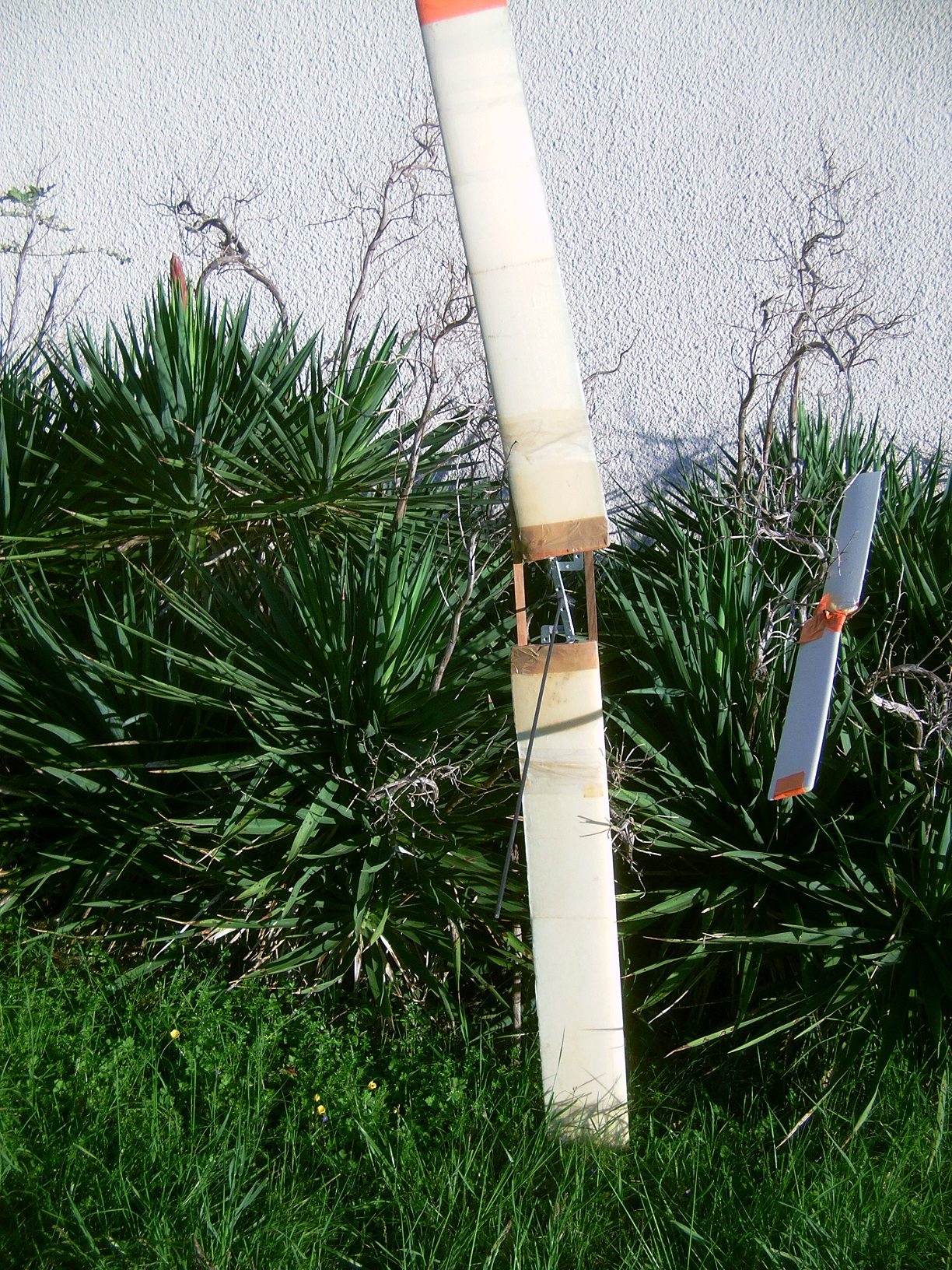
With about 20 m two lines, there was no take-off or/and the flight was about 1 second.
When I held it with about 2 m two lines, it went from one side to the other very quickly, being uncontrollable.
If the two rigid wings were connected it would be different.
1 Like
Way back when…
This video shows a disgustingly cheap & haphazard implementation of what can otherwise be a good design
This was one of the scariest AWES tests I’ve flown.
This calamity was a good early indicator that multiline and network formations have advantages when shit goes wrong. Bizarrely it keeps working and holds together.
A bit like me really…
I’m still completely skint but I make much better kites now.
1 Like
We attempted to mix rigid and soft and experienced what we affectionately refer to as “the angry chicken”. What a mess it was! Similar design to what Pierr eB has pictured above.
2 Likes
So let us produce a collaboratively chicken-farm!
1 Like
I measured the TSR of the two rotors on the picture below. Both are made with Naca12 blades.
The big (two blades 1 m/0.16 m, complete diameter 2.2 m, 0.7 kg) and old rotor was laminated with epoxy. Its TSR was only about 1, with 3 m/s wind speed.
The small rotor (two blades 0.5 m/0.08 m, complete diameter 1 m, 0.05 kg) was not laminated. Both blades were glued against each other with an offset of a few centimeters. The TSR was about 3-5, so much more. I don’t still know why there is such a difference.
I don’t think both could provide lift like an autogyro rotor as on the picture below, where the used rotor comes from a gyrokite.

With 6-8 m/s wind speed I tested the small parafoil lifter kite (0.2 m²) alone, elevation angle of 45°, then with the 55 cm diameter rotor rotating at full speed around the tether via a tubular axis, and after launching by hand: elevation angle of 35° until the rotor (as for the complete gyrokite whose the fuselage adds very little drag compared to the rotor). I have no video because I have only two hands.
I think there is a possibiity to stack rotors around ropes and produce a lot lift with numerous rigid (more lifetime) small elements. But I don’t know if this is really manageable. Particularly autogyro rotors should be launched to start-up in each cycle for reel-out phase. Even with 8 m/s wind speed the autogyro rotor did not start alone, while the two rotors above started alone with 2-3 m/s wind speed.
2 Likes
More info to help you answer that question could come from answering questions like this:
Did you balance the larger (and smaller) blades and are they in line with each other and have the same blade pitch? And what is the blade pitch of the small and large blades?
There are several points. My blades are old and my first intent was to build rotors in Darrieus type.
Then I tried to make two-bladed rotors, without aiming a careful building, using my profiles and some non-adapted material I had, without precise purpose.
So for the two rotors I quickly realized, the profile is Naca 12, which a symmetrical profile that is not really suitable for an autogyro rotor.
The pitch of the small blades (1 m diameter rotor) is about 0°, but a blade is some millimeters higher than the other and with an offset of few centimeters.
For the big rotor (diameter 2.2 m) the support is not precise enough, and the pitch can be different after years.
The pitch of blades for model autogyro can be negative: -1° or -2°.
The pitch of the blades of the black rotor I bought with the complete gyrokite is 0°, the blades having non symmetrical profiles.
Now I would want light rotors producing lift (as for autogyro rotors) while they start-up easily (unlike autogyro rotors). A 1-2 m diameter would allow a better and lighter realization as the rotor would not be full (as for a 8.4 m diameter autogyro rotor). Negative pitch (-1° or -2°) is used to facilitate start-up for some small models, but I think it is not enough for the use I intend, in reeling mode.
The video below provides some explains for starting autogyro rotors:
1 Like
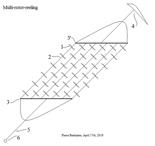
Multiple rotor reeling. Here’s something I came up with now after looking at that drawing. It’s a premature idea.
I haven’t read the reason for putting the rotors in a grid like that, so put all the rotors on a single line, some rotating clockwise, some counterclockwise. To try to eliminate, or reduce the need for, the lifter kite, let’s try to have the upper rotors point more upwards. How about trying to get a more pronounced curve in the line section that has the rotors by connecting the top and bottom of that line section with a shorter rope?
To get the rotors to stop and start… Maybe decrease the length of that extra shorter length line further so that maybe more/most rotors stall? Or mechanically lock the rotors together or to an extra element so that they work against each other?
The reason is allowing implementing more rotors without undergoing collisions with several independent units comprising a single line each. And if the rotors are on a single line, it will be too long. A single line would be a step. That said the complete scheme could be for later.
Now I am experimenting a single line with one then several rotors. Clockwise and counterclockwise rotors are already envisaged to prevent twisting of the line.
For some other points I will see later. There are options you describes, and perhaps other options. The current issue concerns the rotor. Now I can test with my three autogyro 0.55 m diameter rotors but it is limited.
It is very difficult or perhaps not possible to orient the rotors by themselves when they are not connected to a respective body as for autogyros. And without stable lifters the rotors tend to loss lift, as for Daisy without a kite lifter. That could be perhaps possible if the (small) bodies are integrated to the line to reorient the rotors in respect to the line.
And also to increase the elevation angle upper rotors should point relatively less upwards in respect to the line as the elevation angle of the line is already 35°, leading to an already very high angle of attack of 55° if the rotor is perpendicular to the line as it is naturally.
Yes. You’d have them rotate around a rod. You could change the center of gravity of the rod + (vane) + … + rotor to suit some need, or/and you could change the shape of the rod. You could vary the tension of the tether to make the whole thing more or less “rigid,” but I assume the point is to have a tether tension as high as is possible. Perhaps when that tension drops, due to a rope shortening somewhere for example, you could try to use that to stall the rotors.