Towards a viable AWES

There is nothing new in the following design, excepted perhaps later improvements.
It is a rotor with secondary turbines under a lifter. The electric transmission allows reaching really high altitude. The main rope is motionless in order to avoid a too big wear and protect the electric cable. The lifter is also a supplementary safety in the case of computer failure. The rotor allows a constrained figure being not exclusively dependent on the computerized control. The rotor scalability can be a concern but rotor blades for autogiro or helicopter have higher aspect ratios than aircraft wings, and are far lighter. Then suspension lines reduce loads. Critics and observations are welcome.

Except for the lifter kite that is basically what

http://bladetipsenergy.com

is developing - and actually already flying. Since they do not have a force vector from the lifter they do need active pitch control though.

/cb

1 Like

Blades tips energy, a French company based in Grenoble try to do that since 5 years but without a lifter. I don’t think that could work without a lifter anyway. I know the guy, Rogelio Lozano. They already began to pivot 1 year ago to do a radio transmission tower. Might be not convincing enough to go on power production as it is a clissical pivot. Zéphyr solar, a helium solar ballon did the same thing 1 year ago.

If you want to build a small demonstrator of the concept this toy:

might be a good starting point :slight_smile:

/cb

1 Like

The active pitch control of a rotor is complex and expensive. There are two possibilities of doing without: putting a lifter, or making a gyro kite with a body like this:

See also “Centrifugally Stiffened Rotor (CSR)” on


Turbines in the tip of blades take faster apparent wind and can be smaller. I don’t think that centrifugal force is so important in regard to wind force, at least as the rotor scales. So a relatively rigid construction can be better.

1 Like

IMHO http://bladetipsenergy.com is developing a good concept that could be suitable as an AWES. For that some possible improvements are a higher aspect ratio of the blades, the secondary turbines in their tips, adding suspension lines or bridles to counter the bending moment of the blades, and a lifter. After there are some interesting possibilities.

See also their yoyo concept:

See also a sort of gyrocopter suspended from tower @dougselsam posted:

2 Likes

To obtain a (if not the) viable AWES: having wind turbines on a LTA windpower like on http://www.ltawind.com/Main.php?lang=en then combine that with


The second link is on

https://forum.awesystems.info/t/an-alternative-method-to-tap-high-altitude-winds/949/14?u=pierreb
Some interesting points are:
Table 5 Reference photovoltaic plant considered for hydrogen production
and
12 Conclusions: Hydrogen, which can be produced on board, simplifies the management of airship during long missions.

For an AWES I think about photovoltaic panels covering the top of the envelope and ensuring the production of hydrogen to fill buoyant gas leaks by replacing it, and supplying the VTOL which uses the wind turbines on board.

And as additional significant feature: a stationary operation mode with a high elevation angle, allowing secondary use on the ground or the sea.

Such an AWES gathers proven elements from current wind turbines, tethered LTA


, wings, and photovoltaic plants.

We must also consider that no airborne wind turbine project has succeeded in spite of years of R&D and significant funding, and in particular the so-called “crosswind” systems, that due to several obstacles of which a lack of reliability preventing any serious secondary use, and also an efficiency decreased by cosine losses, by irregular (due to the place of the AWES in the window flight) and discontinuous operations, and difficulties for takeoff and landing operations…

So, for this new year, let us wish a new orientation of R&D for AWES.

1 Like

LTA does not point “towards a viable AWES”, but points away; based on my experience in both fields, LTA is for kids and foolish investors, but AWE is for everyone.

It is an opinion, not more.

Let lack of LTA success be the proper test of my opinion.

I agree on the essential. That said Bladetips Energy blades seem to have a low aspect ratio (see below) and a relatively high area, likely in order to assure lift by active pitch control. And also the turbines are not settled in the tips of the blades. So they don’t benefit from the maximum linear speed, and should be larger and heavier to compensate this. See also Blade Tip Turbines topic.

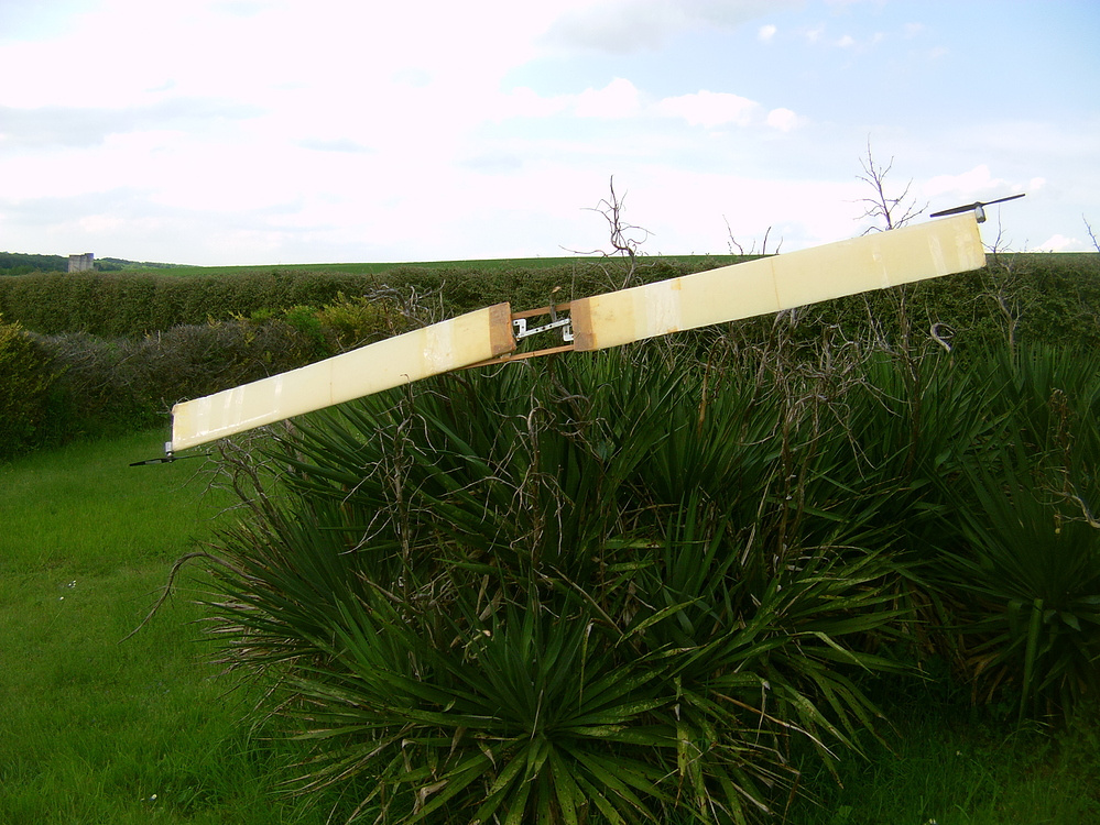
It is the reason why I would prefer blades with higher aspect ratio for a better efficiency, and turbines settled in their respective tips. I put again a photo from quoted topic above. This rotor would be used under a kite lifter as for the drawing in the initial post. Perhaps I could remake it then test, at least its TSR with then without turbines.

Some sketches of autogyro fly-gen AWES.

An unity:

Several unities that are connected by Sharp rotor as separators while providing both aerostatic and additional aerodynamic lift:

Some observations please?

Hi Doug,
Do you mean that it should be the same for AWES? And what would be the spinning devices: only rotary AWES (Sky windpower, Daisy, SuperTurbine ™, Kiwee…), or in addition AWES including fly-gen, as the generators aloft spin?

Hi Pierre: Ever noticed how the name of this “topic” (Towards a Viable AWES) encapsulates every AWES effort? After 14 years, still looking an anything that might be even just “viable”…
You gotta spin to win. That’s all I can say. Taming the wind means you gotta spin. However you do it, you need spin, if you want to win.

Here’s a funny offering for a wind turbine invention. It uses a vertical-axis turbine. But just in case there is no wind, it uses solar to power a motor that spins the rotor. Boy, they REALLY want to spin! Not sure why they don’t just put the solar output into the inverter instead of wasting a motor. But if you read below, Vertical-axis is the fastest-growing segment of the wind energy market (!!!), because wind people still need more time to get used to this superior turbine design concept that costs less to build AND doesn’t need to aim(!) AND is more bird-friendly and people-friendly AND doesn’t need to be mounted as high!!!.
Know why vertical-axis turbines are almost never mounted on a high tower? Because Professor Crackpot believes in doing everything wrong, so if you have a crappy vertical-axis turbine, why risk ruining its crappiness by mounting it on a tall tower? Really, deep-down, they know their vertical-axis turbines are such a bad idea that they know they are not worth the expense and bother of a tall tower. If you are going to use the wrong turbine, why use a good tower?
They think ANY vertical-axis wind turbine manufacturer would love to buy the patent.
SO I guess they need to start with that LIST of vertical-axis wind turbines, huh?
Let’s see, a LIST of vertical-axis turbine manufacturers… Well I guess we can’t find any in the Western World - we’d have to go to China. They are more advanced, so they can sell you a vertical-axis turbine. See how it works? You gotta be on top of the latest information or you would miss the whole vertical-axis revolution!
Here’s the funny thing. We were pretty-much relegated to making fun of vertical-axis turbines until the miracle of AWE emerged.

Hybrid Vertical Wind and Solar Turbine: U.S. Patent No. 8,338,977

\ 15x1
\ 5x1 \ 1x5

Wind turbines are everywhere, and the fastest-growing segment is the vertical-axis turbine. Horizonal-axis wind turbines are simply a newer version of the old Dutch windmills from hundreds of years ago that uses airplane-like propellors. Vertical-axis wind turbines catch the wind and thermal updraft to spin on a vertical axis. Vertical-axis wind turbines enjoy many benefits. They are cheaper to manufacturer and easier to install than horizontal-axis turbines. They do not have to be turned into the wind as they generate power from a fixed position. Their vertical blades turn slower than horizontal blades, so they are safer for humans and birds, and they can be mounted closer to the ground than horizontal-axis turbines.

This patent takes the vertical axis wind turbine to the next level of performance by adding solar and creating solar photovoltaic rotation in a hybrid wind/solar electrical-power generation system. When wind velocity drops, the solar cells provide power to a motor that drives the wind turbines so electrical current is being generated even at low wind speeds. When wind speed is sufficient to turn the turbine blades at the desired speed, electrical power from the solar cells is stored in a battery so it is available when needed after sunset. This configuration creates an electrical-power generating configuration that is far more productive than just a wind-only turbine or just a rooftop of solar panels.

U.S. Patent No. 8,338,977 for a “Hybrid vertical axis energy apparatus” would be a critical acquisition for any vertical-axis wind turbine manufacturer. The invention can be incorporated into next-generation vertical-axis turbines or retro-fitted to vertical-axis wind turbines currently in use. To request the Prospectus for this patent, contact IPOfferings at patents@IPOfferings.com or 845-337-6911.

Among my proposals in sketches or realizations (FlygenKite), I may prefer this one (below) which I have attached to this comment:

Manufacturing and implementation are facilitated by the fact that the assembly is in rotation which also ensures gyroscopic stability. Solar panels could provide hydrogen or contribute to the supply of electricity which is mainly produced via the secondary turbines.

The central lenticular airship rotates with its blades and provide some aerodynamic (in addition to that of blades) and aerostatic lift, and is settled in the middle where the potential of sweeping is lower.

The drag of the lenticular airship slows down the rotation but not too much as the rotational speed is not high compared to that of the ends of the blades.

A cyclic control of the length of the bridle strands is necessary in order to keep the angle of attack ensuring lift during the rotation.

The shape facilitates takeoff and landing by being simple (nothing dangling, and the symmetrical shape, including that of the lenticular airship, are assets), and by using secondary turbines as motors-propellers.

A variant with longer blades and a smaller central lenticular airship is a possibility:

1 Like

Airborne wind energy is finally ready for lift-off (energymonitor.ai)

1 Like

I forgot one detail that I had experienced: the internal lenticular balloon, also illustrated with its recent video, only slightly slowed down the rotation of the assembly, but the blades were not very efficient and the Tip Speed Ratio (TSR) was low.

Things were different with the 56 cm diameter two bladed rotor with a 25 cm diameter ring in the middle: here the TSR of the propeller alone was significant, and the 25 cm diameter ring considerably slowed down the rotation of the whole, in spite of it is a profiled disc designed to spin when launched.

In this way one of the expected advantages of a lenticular balloon (moving the blades further apart so that they sweep a wider space) is most likely negated by the drag generated by the rotation of said balloon (with the blades around).

So I’m back to the design that could include a central round kite or balloon, but fixed and well bridled, with blades rotating around, which may require two counter-rotating rotors.

I think that by making the central part of the balloon or kite or both as wide as possible, we will be able to make progress in the area of scalability, while at the same time having a maneuverable machine that can take off and land, and that can be sufficiently mobile to be able to move to better winds by anchoring at a different station.