What is possible with Payne's patent US3987987 figure 5?

No Pierre, there are already massive mining vehicles with autonomous-driving modes. Its true that rail-tracks and carousels are capital intensive, but they are readily automated too.

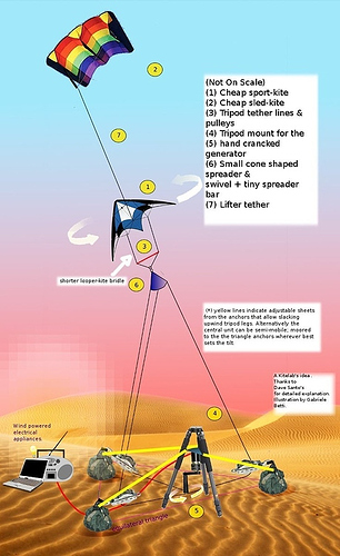
Again, the tri-tether is Fig5 in 3D, and eliminates belay while accepting wind from any direction.

As a temporary conclusion of this topic, and spite of my initially rather favorable opinion about the studied system, some bottlenecks occur such like the pulling force that is not well oriented or the added devices to allow facing the wind directions. And the implementation is rather complex compared to the pumping mode. So building them looks unlikely.

Again, we must add the cosine concern to the aforementioned problems What is possible with Payne's patent US3987987 figure 5? - #10 by PierreB .

Pierre, Fig5 is far less complex than Makani’s architecture, and many schemes you have favored, like OrthoKites, WheelWind, and RotatingReels. At least kPower can handle the obvious low-complexity, by developing the methods diligently-

image

The real complexity crisis is active flight automation of single-line flygen and reeling in breakaway-mode. Fig5 passively retains the kite if one line breaks. No flygen or control-pod dependencies and vulnerabilities. This inherent simplicity is what Low-Complexity AWE is all about.

I critic my own schemes as well.

Active flight automation would likely be required, whatever the used scheme, even if some level of passive control is highly desirable.

No one is arguing that the passive-control kite schemes should not have automation when it is available. Its just not yet available, but kite pros manually fly giant kites already. I like both manual and automated AWE. Manual is more fun, less pain.

Fig5 is less complex than virtually all other schemes, by standard metrics of engineering-complexity (part-count, state-space). Fig5 is the simple original idea in the Low-Complexity AWES design space. How grand it will be to fly 1000m2 power-kites hands-on, before automation is ready.

Makani’s architecture is the prime example of High-Complexity AWES thinking, where flight automation is an inherently critical requirement. No great RC pilot wants to be at the joystick crashing an M600. Better to hook up computers and blame programmers, never the mistaken architectural down-select.

Fig5 is AWE’s Cinderella Architecture.

I will qualify my last remarks. The favorable development of the Figure 5 does not seem obvious to me. However the tri-tether configuration as conceived by Dave deserves to be investigated. There is a picture below and some links about a tri-tether rig:


https://iopscience.iop.org/article/10.1088/1742-6596/1037/4/042023/pdf, the same on
https://www.researchgate.net/publication/325833533_Assessment_of_an_Alternative_Concept_for_a_High-Altitude_Wind-Power_Generator.

The figure 9 represents the curve of power for a 20 m², 5 kg paraglider at different wind speeds. The value of 6000 W at 9 m/s wind speed is about from 60 % to 75 % the expected average value for the same kite in pumping mode. The continuous power can compensate the lower value. Other advantages can be expected such like a better safety thanks to the three tethers.
Pierre,

My Tri-Tether work was precisely the “favorable (3D) development of Figure 5 (2D)”. I must give credit to Payne, who lived in Annapolis, MD, where I also lived, back in 1975. JoeF and I are in occasional contact with the family. We propose Payne’s (and McCutchen’s) estate(s) someday be compensated, as the inventive contribution is recognized, never mind the patent IP has expired.

My drawing was not accurate as the kite moves in loop.

In fact I extrapolated from idealized values of a pumping kite. The paper linked above specifies that both are comparable in term of expected power. We will know better if tests are made.

Thanks for the precision.

Pierre,

There is an extra tuning parameter to tri-tether rigging that enables optimal crosswind load-path geometry. KiteLab Ilwaco solved this state-of-the-art advance from the start.

AWELabs of Austin (Leo Goldstein) provided a rigorous mathematical basis for fig5. Various other parties have identified and quantified tri-tether potential.

Don’t lose sleep over whether fig5 is a major contender in the AWE Race, despite the fact no AWEurope venture has yet tested the idea.

https://forum.awesystems.info/t/fig-5-of-payne-and-mccutchens-patent-us-3987987/1140?u=pierreb

image

Such a simple and straightforward concept, and yet nobody bothers to build one…
Why?

It’s a matter of geometry. The amount of tension applied to the tether vs the kite pull vs the speed of the line on the reel… I challenge anyone to put forth a probable calculation for a working design. Then start discussing soft vs rigid etc.

The calculation could assume the kite pulls with any force, then describe the geometry of the triangle and how fast the kite needs to fly in order to generate x kW…

1 Like

In yoyo mode, the pulling force is converted in energy, unlike (at least partially) Figure 5 configuration.

Let us analyse a bit what we see on the video below (also from kPower LLC filing - #58 by kitefreak), just after the indications:

If we see carefully the system during these 9 seconds in full screen and with stops, we can see the two anchored pulleys at the left and right to the skateboard, and the triangular rope sliding during the flight and moving it.

So, Figure 5 has therefore been made and shown on the video above.

I can observe that the range of motion of the skateboard is very limited. I could deduce that the applied force by the kite looks to be limited as it is not directed towards the move of the skateboard. A large part of the force is lost due to the traction exerted on the anchored pulleys instead of actuating their rotation. Thus a minimal part of the force is applied to the displacement of the skateboard.

My point being that the pull difference along with the speed of the two tethers must be enough to produce sensible amounts of energy, without demanding a very thick tether with lots of drag to do so… I think to comment one would have to describe an experiment like I suggested

Fig. 5 of Payne and McCutchen’s patent US 3987987

Focus our engineering talents over the seed of Fig. 5 of Payne and McCutchen’s patent US 3987987.
US3987987

PTO options?

  1. Saw wood, marble, etc. by use of line segments made of cutting materials.
  2. Produce heat by having part of the line segment involved in heat-production arrangement.
  3. Have an electric generator in just one of the anchor places.
  4. Have electric generators in both of the anchor places.
  5. Have flygen mod with PTO means in the wing set.
  6. Have flygen mod with PTO means in the upper lines.
  7. Shuttle transport materials or people, etc. from L to R.
  8. Have wheeled vehicle on ground being shuttle where wheel axles drive electric generators perhaps to charge batteries; the energy might be used to drive the wheeled vehicle when taking the vehicle off the ground line of the Fig. 5 arrangement. See Santos’ powered skateboard demonstration.
  9. Pump fluids via configuring the ground-line segment with adaptations.
  10. Tug rafts or hull back and forth over a body of water or river.
  11. Waft a lever to get mechanical advantage for crushing things
  12. Pump air to a storage chamber for energy storage.
  13. Rub/polish faces of flat-stone surfaces.
  14. ?

Wing-set options

  1. One wing in wing set.
  2. Two or more wings in wing set in loop.
  3. Two or more wings in wing set in stack style
  4. Soft wings
  5. Semi-rigid wings
  6. Rigid wings
  7. LTA wings
  8. Motor-powerable wings
  9. Mixed-type wings in one system
  10. ?

Anchor-set arrangements

  1. Sea systems
  2. Land systems
  3. Sea and land systems
  4. Aerial FFAWE systems [FFAWE : free-flight airborne wind energy]
  5. Turret
  6. Manual belaying
  7. Floating anchor base allowing desired wing-set wind facing
  8. ?

Tether-set options

  1. Fixed tether length
  2. Variable-tether length
  3. ?

Farming the schemes

  1. Lateral repeats with sharings of anchors.
  2. Arch height differences for repeats.
  3. Windward repeats.
  4. ?

These horrendous old animated sketches give a modest idea of what was intended in these schemes.
Recommended 2x speed watching


Shows a kite control bar with 3 pulleys on one side of a field, controlling a kite on a line loop.
The single loop trifurcates into the 3 pulleys on the left hand side (looking from upwind)
The loop goes round a capstan/pulley on a generator ground-station at the right hand end .

Moving on

It was better than this earlier one

However there’s an even worse and older animation available with more insight to the scaling suggested in these schemes…
In this example either the whole net was meant to deform to sweep the load line loop left to right…
Or each kite cell (kixel) on the Mothra arch of kites was to be steered … so that the collective would move right to left to right…

I tried rigging a bit of collective panel/sheet steering to mimic the physical action needed for this… eugh yuck it’s a sticky affair.

1 Like

The useful energy of any AWES is that which rotates the generator. I do not think the figure 5 describes a favorable configuration. The problem of tether drag comes later if it occurs. The reeling (yoyo) mode looks to be far more efficient as the pull of the kite is fully used, unlike the device represented on the figure 5.

1 Like

I think the main difference between yo-yo and fig5 is scalability

Let us compare the two videos of 9’’ each from Random interesting links and from kPower LLC filing :


The first video shows how the pull of the kite moves the cart in its direction (as for the yoyo mode, the reeling replacing the move of the cart), while the second video (figure 5) shows how the pull of the kites remains mainly in the tether. As a result the power is better applied on the device represented in the first video, and this is very visible in spite of no use of crosswind power.

The videos are funny/cool, but can not be used to analyze drag vs lift mode AWE. You need a proper wing, proper reelout etc…

1 Like