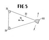
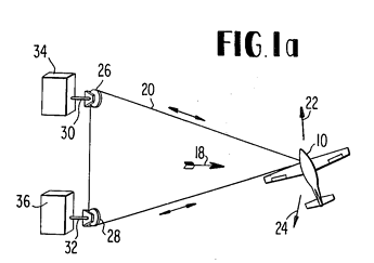
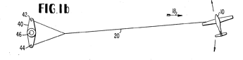
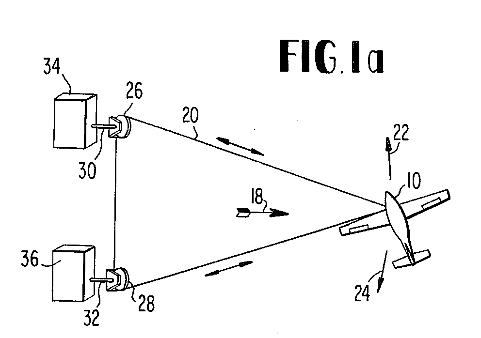
A general lack of transmitted pulling force occurs by using two anchored tethers simultaneously, as for figure 5, and also for figure 1 a and figure 1 b, leading to a partial cancellation of the tangential force that rotates the system.
It is the reason why I studied a lever transmission when the tether is perpendicular to the lever in order to maximize the tangential force that rotates the lever. See the video below where the two tethers work alternatively.
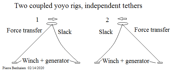
In fact the same power transmission would be obtained by using two coupled yoyo rigs.
In some way that can be correct, but the problem is that the energy is not taken on the wing but on the ground, with the lack of useful transmitted force I mentioned.
The two videos that I juxtaposed in a previous post only confirm visually the analyzes that I provided during my last messages.
As conclusion the systems represented on the figures 5, 1 a and 1 b are less efficient as the yoyo mode.
Fig5 is a normal drag mode rig. It should fly at 2/3 the speed it would unloaded. In order for this to happen the angle from the rear line must be at an angle to account for this and for the glide number of the kite+tether. I believe the triangle cant be very tall for this, I would very much like to see some real numbers for this.
If the tension of the two tether is more balanced, eg. ratio 1:2, the triangle must be even lower.
So anyone promoting this idea, please start with these numbers, otherwise there’s really no point in proceeding. The numbers are not clear at least to me.
The geometry of the triangle will definitively affect the usefulness of the patent, as you need also to account for changing wind directions.
We must also consider that some tether strength is wasted, and double tether will cause significant added drag for some altitude of operation. Actually I think all the pull in the front tether is more or less wasted.
Finally the pulleys add some friction, relative to the amount of tether pull wasted.
The reason that I wrote “mostly” pure drag is the fact that the distance from the pulley line to the kite is changing quite significantly during the sweep, if the triangle is wide. So the kite will not be moving entirely linearily, but rather at faster and slower speeds.
I am not saying this idea is good or bad, but unless someone calculate these things for me, its just too much hassle to look into. Perhaps I might anyways later…
After taking a look on the figure 5, I can state it leads to an inefficient device, even without taking account of its unsuitability for changes in wind direction. As I detailed on my analysis the kite pull mainly acts to stretch the tethers, and only a little to rotate the generator system. So making calculations is not needed.
May 2018 Journal of Physics Conference Series 1037(4):042023
DOI: 10.1088/1742-6596/1037/4/042023
LicenseCC BY 3.0
Max Langbein
Maja Ruby
Nicolas Gauger Quoted:
Abstract. To generate power from high-altitude winds, concepts using kites or planeslinked to the ground with tether are in development. The most popular high-altitude wind generation concept is one using a flying wing attached to a single tether whose movement generates power by turning a winch. The usual trajectories for power generation consist of a period where the kite distance is increased, and the pulling force enlarged by figure-of-eight movements, interrupted by a pull-back phase where power is consumed. We comparethat with a new concept we introduce here. It uses a triplet of tethers whose length sum is kept more or less constant using differential gears, resulting in a trajectory surface. It does not have a pull-back phase and allows to have similar power output in a closed trajectory. Moreover, starting and landing can be achieved without additional equipment when using a soft kite as wing, and keeping the wing flying without any wind is easier. Also the control can be easier, as one has more degrees of freedom in the force direction and the movement of the kite. Its disadvantages are an increased effort for the ground stations and more restrictions on the location. Also the tether’s air drag is increased. Optimal power generation is compared using an example configuration and state with given wind speed under the assumption of an optimal steering of the generators and the kites. This is done for state snapshots, for example trajectories, wind speeds, and kites.
(PDF) Assessment of an Alternative Concept for a High-Altitude Wind-Power Generator. Available from: HERE [accessed Feb 12 2020]. For convenience, I quote the paper for its use of the following symbols: 1r one-tether, angle of attack optimized, distance is allowed to increase, 3r. three tethers, angle of attack fixed, distance (tether length sum) fixed, 3r three tethers, angle of attack optimized, distance (tether length sum) fixed.
Quoted:
“4. Discussion & Outlook
It has been shown that: 3r is comparable in terms of power output. 3r makes it possible to have a kite with constant angle of attack. 3r makes it possible to land and start the kites without additional equipment. 3r makes it possible to keep the kite airborne when no wind is present.
A key feature of 3r could be a constant power production which could be achieved by steering the distance motor-generator accordingly while keeping a closed trajectory. An optimization achieving this would proof the value of this new concept. To increase the precision of the evaluation, acceleration forces based on the trajectory should be included and whole trajectory optimizations should be done.”
When in a Fig.-5 AWES the loop segment that slackens might be considered during that slack as a non-tether, but line laundry with its mass and drag; the active wing set and taut working line parts tether the wing set and lifts the mass of the slack line. The line laundry drag and mass will combine to add tautness to the working non-slack tether. Suppose one could magically periodically fully delete the slack section; the working wing would still be just itself, though be flying a bit higher. But we do not do that magic deletion; we just let the slack section lower the altitude of the wing set a bit.
Flying the wing set in cross-wind cycles and having PTO at the ground seems to keep the system a lift-based AWES.
I provided this link on Tri-Anchor Tri-Tether AWES Unit-Cell. The geometries of the AWES represented on the figure 5 and the tri-tether AWES are different I think.
I think the tether network anchored in 2 points (figures above) or 3 points (tri-tether) acts simultaneously on these points, all lines composing the tether network being connected. As a result a significant part of the force is an useless parasitic force.
FIG. 1b describes a lever with a strand stretched at each end, and which can be easily tested: the pull on the rope and its perpendicular move to said pull will have a minimal effect on the rotation of the lever. This is the reason why only one strand is in action on OrthoKiteBunch, the other being slacked. But that supposes an active control on each of the two winches respectively located at the two ends of the lever, and therefore more complexity.
Hi Tallak, thanks for asking.
It’s an endorsement of actually trying things, rather than endless online speculation through typing on a keyboard.
What, with over billion dollars wasted so far, nobody bothers building even the most rudimentary version of the most straightforward “crosswind kite” configuration imaginable? People just talk about it for 12 years and ever build one? WTF? What’s the matter, not enough idle interns yet? Not enough volunteers in Texas? Seems that the population is being dumbed down by computers. No more machine shop skills. Forget that troublesome, challenging 3-D world. Build something? The main skill I see now is website development, meaningless renderings, and how many people you can fit into your group-selfies.
Better than no video at all, possibly suitable for an elementary school science-fair effort, cub-scout project, etc. It would be nice to see a serious effort.
Oftentimes people figure out that something will probably not work great on paper before they actually spend months to get it working. This is why something ready built and working is worth a lot more than a nice idea.
For the Fig5 design, i am still unsure if it could work. The design is interesting for sure, but I am guessing there might be some showstoppers in there that are not apparent from looking at the patent. So the reason it is not yet built could be that building such is not a great idea in the first place.
I think what confuses a lot of folk, and also is the biggest potential for tangle, and efficiency loss, and control overhead in this idea …
Is that there is different tension on the 2 sides of the loop…
Lets say we have only 1 generator (Left Hand Side) and one perfect pulley (RHS).
We have 1 loop of line with 2 (or more) tension levels because the pulled side of the loop (LHS) goes over a drum or a capstan (LHS) which has to restrict the movement of the rope to extract energy…
You can’t push rope. So the end going toward the pulley (RHS) … well it’s not doing it very effectively with push, it’s being pulled. Which uses more energy. Along the rope there are different tensions where it’s movement is being restricted.
The kite will be moving… but mostly with respect to the (LHS) capstan. Now with 2 capstans… You won’t have as much tension control authority from the (RHS)
Getting it to go crosswind… Like actual cross-wind not science-crosswind which is real world cross-off or a broad reach… #AWESScienceSucks. Getting it to go crosswind … That would take a lot of cable tension and length management equipment between the 2 sides.
Of course there’ll be friction on both sides. Smaller wheels will mean lots of line wear.
So the end of the loop pushing in toward the (RHS) That’s going to bundle up and snag horribly if you take too much power out on the (LHS)…
It’ll work when you don’t take full power out… But what about gust and lull handling?
Disconnecting the tethers avoids simultaneous traction on the two elements on the ground, in a similar way as for Tri-tether plant with independent stations. However, the device shown below does not adapt more to changes in wind direction than the device shown in FIG. 5
If you want this, I would say whats the point unless both lines are somewhat taught. If you so that you can have crosswind linear motion. Otherwise is it not just a complex yoyo design?
If you use two motors, there are conversion losses. Even just creating a static force (zero energy at zero or near zero tether speed) may incur large losses. This is why pulleys are better.
But balancing two or more tethers like this with pulleys is a bad thing because all that force+counterforce must be generated at the kite then transferred to the ground. So if you regard tether drag as a large effect, this already sounds bad.
The topic is “What is possible with Payne’s patent US3987987 figure 5”, just as the neighboring topic is “Tri-Anchor Tri-Tether AWES Unit-Cell”. So my propositions have to be considered in regard to the devices discussed on these topics, not in regard to the full AWE field.
As I indicated, these devices with several anchorages are complex and likely not viable whatever the variant implemented. As I am not the type to give a mixed opinion (as much not to give an opinion at all), the more I analyze these bi or tri anchored devices, the less I see them a positive future.
The yoyo installations as they are generally studied seem to me both simpler (only one station / kite /tether) and more efficient in terms of force transfer and management. Which is not to say that I think they are viable.
That said it is quite possible to obtain a slack tether with no transfer force when the stretched tether is longer during its reel-out phase. The expense of energy in alternate reel-in phase is equivalent as for current yoyo rigs, knowing that a continuous power is aimed. Is it good for all that? No, but I think it is the only way to actually transfer the kite pull, unlike pulleys because they are connected by a part of the tether network, the assembly preventing a correct transfer of the kite force.
The main benefit I see from using the pulleys as shown is the minimization of the tether drag issue as the kite will not go very fast in this tether yoke.
How about a rope drive stretched along the ground with the tether of your kite attached to the rope from the rope drive? That’s what figure 1b reminds me of a bit. To avoid the tether deforming the rope too much you can add bridling.
I’m just talking about two pulleys separated some distance across the wind, a long rope loop, a generator. Try two pulleys before worrying about three pulleys.
You could build it and run it faster than doing a single rendering.
Budget? Probably in your pocket right now if you already have a kite. If not you’d have to spend a couple hundred. Entire project could cost less than $1000 using decent components.
Again, most configurations could be built and tried with less effort and money than even just applying for funding. Nobody bothers.
What’s so hard about it, finding pulleys? A rope? Suddenly no generators exist?
Or is it that you can’t do it from your i-phone?
Dave already built a working prototype (video below again) of the US3987987 figure 5 AWES as I repeat. Please @dougselsam could you read the other posts before comment?

")