Zhonglu High Altitude Wind Power Technology - 中路高空风力发电技术

Zhonglu High Altitude Wind Power System Trial on Site

A little more info here: Slow Chat - #71 by Windy_Skies

Interesting video. Some other discussed points (comprising a link to their document chinese umbrella description.pdf ) are on The most basic airborne wind energy system - #15 by PierreB.

A link goes to Guangdong High-Altitude Wind Power Technology’s parachutes.

I presented also an option by replacing the parachute with a flexible rotary kite.

If this is verified, would this be the most significant electricity production made by any AWES?

1 Like

In the video you can see they are generating no more than 22kW. They’d need to generate around 600kW to get to 30MWh in 50 hours, and they would have done that in 2015. Verification needed I think. But then all that money must also have gone somewhere.

This looks like a promo video shot in a single day and in little wind, perhaps to get nice drone shots. What happened after this? The bigger news I think is that they’ve now got some funding to do more research.

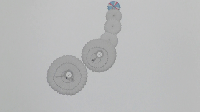
If this picture from their website is real and they flew it in stronger winds they might have generated some power. And then times four if they flew four of these at the same time. But it would have cost some power to reel it in too if only 2 of the parachutes could be collapsed. One wonders about the size of the lifters or balloons to maintain the tether angle in higher winds.

3.2

2 Likes

chinese umbrella description.pdf page 12:

Normal force coefficient VS Angle of attack ɑ
CN /CT< 0.01
N/T< 0.01
Wind Tunnel Result
The required lifting force to keep an opened umbrella’s angle of attack constant is very small
compared with the polling force it generates

But already significant flying bodies such like a balloon and at least one static lifter parachute assure required lifting force to the working umbrella(s), and under an apparently low wind. For a small required lifting force, small lifters should be sufficient, or there is something I do not still understand. The angle of attack could be connected to the tether angle in some way.

1 Like

I wonder why so much time is spend on crosswind flight if the same amount of power can be generated with a slightly bigger kite / parachute

1 Like

Welcome to the forum @Ewout

Good question! The response is not obvious. I think almost all scientific circles reason in terms of power / wing area ratio, following the seminal Loyd’s publication: Crosswind Kite Power.

On this criterion, crosswind flying wings are much superior to parachutes, according to a lift to drag (L/D) squared ratio. This ratio still increases when the wing is rigid, leading to increasing of the L/D ratio.

Now if power / weight aloft ratio is applied, things are different.

And now if Power to space use ratio is taken into account things can be still different: the path of a crosswind (above all rigid) kite is far larger than the useful swept area (being able to be the parachute area) due to the flight requirement; and within a kite-farm very large spacing between unities (and also the inhabited areas) is required due to safety needs as they fly fast.

So in the end a kite-farm using parachutes flying slowly could be denser…

2 Likes

Thanks Pierre.

I see the relevance of crosswind flight for utility scale deployments.

But let’s consider a small scale deployment ,such as the 10kw Eaz turbine below. Turbines like these are popping up next to farms all over the country. Instead of expensive electronics it uses purely mechanical controls to become cost competitieve. A big fin to face the wind and tilting blades as a overspeed protection.

If you would apply the same design strategy to a let say 5 kw AWE system. What will it look like? I think you will end up with something in between the traditional paradropper kite and the Zhonglu concept. A lifter kiter, a parachute that flags out when it reaches a certain hight/obstance and a ground gen. No airborne controls needed.

http://www.dickwightman.com/kites/rainbearskydivecorps.htm

About the Parachute Aerodynamics (pages 10-15) on the chinese umbrella description.pdf :

The angle of attack is also the elevation angle, perhaps because for a round parachute the center-line is considered.

On the drawing page 10 the elevation angle (= angle of attack) is 30 degrees.
Page 11, the angle of attack varies from -30° to 30°. At 0° the tangential force coefficient is 1 (and is also the drag force coefficient), being maximal at 30°, so 1.2, that with an imporous canopy.

Thus the used terminology (tangential force coefficient versus angle of attack…), the porosity issue, and also, although not specified as such, the specific definition of the angle of attack as the elevation angle, match the contents of the publication Stability and drag of parachutes with varying effective porosity :
https://citeseerx.ist.psu.edu/viewdoc/download?doi=10.1.1.888.9178&rep=rep1&type=pdf

Pages 19, 44 and 47, with an angle of attack from -30° to 50°, the tangent force coefficient decreasing from 30° to 50° (page 44: 0.58 to 0.45; page 47: 0.6 to 0.5).

Page 19, from -30° to 50° the tangential force coefficient varies a little (0.7 at 0° to 0.75 at 35°, then 0.7 at 45°).

Page 2: a) The tangent force, T, acting along the centerline of the parachute. This is a drag force at zero angle of attack.

I would like to propose a simpler umbrella system. Instead of four separate windup stands why not have a single shaft with four unwind reels on it. Each unwind reel can be decoupled from the shaft and rotated in the opposite direction to retract the umbrellas. As shown in the attached sketch, the length of the shaft will only be about 9 meters with 4 meter diameter umbrellas. For wind changes, we must rotate the whole shaft so the whole device must be located on a turntable or carriage. This is preferable to having idler pulleys to redirect tethers which reduces power and causes wear on the tethers.

What intrigues me about the Zhonglu design
When it’s done the power stroke… The parachute line end controller let’s go of the main tether. The parachute flags out and the tether line is then retractcted…
So then
How does the controller get itself reset back to position, lower down the tether, without fighting the whole force of the inflated parachute?

I rather think about only one unity or two (for continuous power) separated unities with larger parachutes (or even groups of parachutes) like on the four following links, each parachute being about 115 feet (about 35 m) diameter (so 960 m² of projected area), and weighing respectively only 300 pounds (145 kg) and 200 pounds (90 kg):

The parachute is deflated as shown on the beginning of the video, then at 0:45.

So, I’m not convinced that this is what we see in that video at 45 sec.

That little control pod is somehow able to crawl back along the line, whilst pulling the parachute and lines back down to the main catch point on the line to reset.

Listen to the commentary in the Orion capsule recovery video… Tens of thousands of pounds of force on those parachutes when they inflate. There’s a very fast transition in the Zhonglu video from deflated to inflated. That would create a shock load on the capsu

Is this another AWES company with a reversed footage?

1 Like

I deflated 400 m³ solar balloons by using an internal central rope, and by freeing the traction rope for the lines of my harness: it was enough to wait 2 or 3 seconds that the wind or the aerostatic thrust made the balloon turn over like a sock, deflating completely without effort.

So I think Gangdong system can work.

Also a parachute valve for a hot air balloon could perhaps work, the wind pressure putting it back in place after deflation by traction. But I prefer the internal central rope.

1 Like

Thanks @PierreB
Do you see that technology on the Zhonglu parachute?

My system of internal central rope was rustic. Zhonghu parachute looks to use a similar principle (central deflation) with a pod moving upward while winding the summit rope (my internal central rope), sliding around the main tether. So there is several ropes, as shown on the drawing below. I think this system could be simplified, and perhaps being passively automated.

Available links to their patent:

https://patentscope.wipo.int/search/en/detail.jsf?docId=WO2010129124

https://worldwide.espacenet.com/publicationDetails/biblio?II=0&ND=3&adjacent=true&locale=fr_EP&FT=D&date=20101111&CC=WO&NR=2010129124A2&KC=A2

1 Like

Indeed inflation can be more or less problematic, unlike deflation. But the shock could be mitigated if the maneuver is progressive (2 or 3 seconds at least).

To get that 2 or 3 seconds on a typical parachute you want a slider over the rigging lines

That’s probably harder to implement on a round chute with many more lines.

That is probably the peak power you see on the screen.
Or
Maybe it is power used to retract…

By a brief and rough calculation (below), it would take about 10 000 m² of parachutes to produce 400 kW with 10 m/s wind speed. That’s a lot, it’s too much, it’s way too much. And the elevation angle of a parachute is not very high, being about 30-35 degrees (?) or about 45-50 degrees for my small (1 m diameter) bear parachute kite.

10 000 x 1.2 (air density) x 2/27 x 1000/2 (reel-in phase) = 444 kW.

2 Likes