A "crackpot" design

Some extract of the last interview:

_What do you plan?
_Simulations are promising. As we are careful and informed 50 small 100 MW unities will feed the East Coast.
Indeed we prefer begin small before starting GW scale.
_ You plan it for when?
_ The next year.
_ But you told it one year ago.
_ Right, we told “the next year” one year ago, then now we tell the same, always “the next year”.
_ And now, besides “the next year”?
_ We are studying a project for remote areas.

The downwind rotor contains blades with variable pitch, producing the stall-returning effect. The flow is not slowed as for devices that are subject to Betz limit. By the stall-returning effect the flow bounces back as soon as it crosses both rotors, keeping its kinetic energy. So the flow is multiplied in layers as the Betz limit is multiplied, becoming 2.5 instead of 0.59, but not more due to the losses by bouncing back. The Cp is expected to be about 2.

Here is a topic for Crackpot thinking and projects. What about a reeling Magnus rotor connected to a Darrieus turbine?

Hello Pierre: Connected in what way? What do you mean?

Hi Doug,
I tried to gather some crackpot features (Magnus rotor, Darrieus turbine, reeling).

More seriously (?) the figure 4A represents a Darrieus rotor (460) around the (not reeling) Magenn balloon https://patents.google.com/patent/US20060251505.

In a similar way, but not as an AWES, the figure 53 on http://students.iitk.ac.in/projects/wiki/lib/exe/fetch.php?media=2014:seifert_flettner_apps.pdf represents an Hybrid rotor comprising a cycloidal propeller around a Flettner rotor.

Oh OK that’s what I thought you meant.
Looks like it would work GREAT as long as it remains as ink-on-paper, where everything does what you want it to, rather than doing what it does.
I would say the wind-shadow of the sausage-cylinder would beat the Darrieus blades to death.

This is probably true.

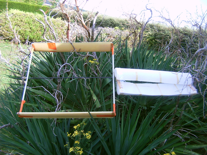
I experimented a rough (attached photo) and not very efficient Darrieus rotor of 0.5 m x 0.5 m, blades Naca 12, carrying on a side an expanded polystyrene Savonius rotor of 0.27 m diameter and 0.5 m span, and on the other side an expanded polystyrene cylinder of also 0.27 m diameter and 0.5 m span. The weight was above 0.5 kg: with a wind of 5-7 m/s the set had a small elevation angle of 10°.

Then the test was made without the Darrieus rotor, with only the Savonius rotor for an elevation angle of 35°- 40° as a kite; then with the Savonius rotor and the cylinder side by side for an elevation angle of 40°.

1 Like

I wish you could post some more photos of your setup. This looks super interesting, but I am having trouble visualising what you have done here.

While many of the papers listed are interesting, my feeling is that they are a bit off. Here is my thinking on the subject (which I hope may be useful for your project):

  • like a wing for a plane, keep the aspect ratio long, eg >5 to mininize the effect of the tips
  • the different technologies datreius, savonius and magnus cylinder all have slightly different optimal TSR. The diameter should be matched so that each section is running optimally (eg a savonius rotor should have 1/4 radius of a darreius rotor, or similar radius to a magnus wing)
  • the area of the kite must be dimensioned so that the power into the magnus wing section(s) must be equal to the power generated by harvesting sections

I am assuming they are all fixed relatively in rotation sharing a single shaft.

The TSR values and harvesting energies may all be found by looking up tables.

Interestingly, the optimal harvesting device here is not the one approaching the Betz limit, rather the one producing most power for the least drag and weight. Probably this would mean high efficiency wings, I believe favoring a HAWT over darreius over savonius. And actually I believe a scaled down turbine like @Rodread’s Daisy might be a good option, with a gearbox.

So I just introduced using rotational AWE systems for on-wing power harvesting.

Let me explain some reasons why:

  • weight to power may be excellent
  • the turbine will self inflate and find its own shape without further rigid structure
  • you are not looking to go high altitude
  • you probably dont need the lifter, or at least it may be tiny
  • with effective blades, the drag should be the smallest of the competing options (that I am considering right now)

Super envious that you are getting some testing done. Looks like fun. Unfortunately I am super time constrained these days myself…

On my previous post I spoke about a 0.5 m x 0.5 m Darrieus rotor with a 0.27 m x 0.5 m Savonius rotor on a side, and a 0.5m x 0.5 m cylinder on the other side.

Unlike a Magnus rotor (and in some way a Savonius rotor due to its Magnus effect) the Darrieus rotor does not need a high aspect ratio.
Theoretically the spin ratio of a Magnus rotor can go with the TSR of any device assuring its rotation. Practically (and according to my rough experiments) exceeding a value of 1 is difficult without motors, leading to a higher diameter of an efficient wind turbine in regard to the diameter of the driven cylinder.

On the photo I attach it is the same Darrieus rotor (0.5 m x 0.5 m) and with a smaller (0.17 m (instead of 0.27 m) x 0.5 m) poly Savonius rotor in the right to allow a better understanding. In the left there was a 0.27 m x 0.5 m cylinder.

As the TSR of my Darrieus rotor was rather low, between 1 and 2 at the best, the proportions between rotors can be too approximative.

However the Darrieus rotor adds drag, and has no lift unlike the Savonius rotor at least with the following dimensions I experimented:

  • a (0.27 m x 0.5 m) Savonius rotor alone leads to 35° elevation angle;

  • (0.27 m x 0.5 m) Savonius + cylinder rotors lead to 40° elevation angle;

  • the same cylinder + (0.5 m x 0.5 m) Darrieus + the same Savonius rotors lead to 10° elevation angle.

In fact the Darrieus rotor(s) could fly but with longer Magnus rotor(s) or/and Savonius rotor(s) or/and Sharp rotor. In the other hand the Darrieus rotor is more efficient than the Savonius rotor for electricity production: an appropriate balancing between these rotors could be studied, comprising their respective diameters and spans.
It would be true if all components (Darrieus and Magnus rotors) have the same diameter. But the diameter of a Darrieus turbine is higher (you confirm this by the TSR requirement), so some rigid structure is needed to hold the blades. And for a HAWT a mast as axis is needed.

However Magnus and Savonius rotors can have the same diameter, but a Savonius rotor is not easy to build in soft material and will be still less efficient. And the Savonius rotor TSR would be a little slowed down by the Magnus rotor.

At small scale HAWT + Magnus rotor would be a possibility, but at higher scale an inflatable balloon like Omnidea’s in reeling (yoyo) mode could be a better solution, but with some needed adaptations.

1 Like

Another possibility would be to place the motors at both ends of the balloon as for Omnidea balloon, but inside the balloon, with the effect of recovering the heat generated by the engines and having a little aerostatic lift. If the balloon is in Tensairity ™ + ETFE, the transparent ETFE membrane retains more infrared and allows more heat to be retained. On the other hand, as the balloon would only be held at its ends, it could not scale much, unless the two types of rotary drive were combined.

Me too. A super Crackpot design. Something about a Magnus yo-yo: a balloon rotates in the same favorable direction of rotation during both power reel-out and super (wind speed + balloon speed) power reel-in phases, then both the ground station and the balloon rotate 180° to pursue to benefit from the suitable direction of rotation. The air mass of the balloon allows to benefit from both linear and rotational kinetic energy.

A video of a giant yo-yo:

A sketch of a Magnus balloon yo-yo:

2 Likes

Had wonder when they were go to get around to making a yo yo generator?
Great idea using a Magnus rotor. Is that going to be magneto ferrofluid filled? Or work on snap back function? Much like a reciprocal drive? With the rope fixed to the apex of the cylinder? It normally seen as in a foot powered turning setups. Either a disk or a bobbin. Eg.

a little bit Roman in origins. You get the idea? The bobbin is the orange cable. I cannot see why it would be good on a kite set up. Considering there are collapsible shoots out there. the same mech is present in tape measures as a coil spring.

A crackpot design, certainly, but something sensible if possible. The yo-yo movement is therefore reconsidered, knowing that there are 3 phases:

  1. Reel-out power phase 1;

  2. Then reel-in + reel-out super power phase 2 where the balloon continues to rise while the tether is rewound at the balloon under the yo-yo effect, while the same tether is unwound (reel-out) at generator;

  3. Then reel-in recovery no power phase 3 where the sense of rotation is reversed (see the video where the direction reverses after a round trip), leading to a negative lift by Magnus effect, the balloon stopping before starting a new cycle.

Is it really possible in theory, not to mention practice?

That could perhaps allow the scientists to make their ranges: Magnus effect, air resistance, trajectories, kinematics, forces, linear and rotational kinetic and potential energy…

A sketch below:

But the rotational direction of a yoyo does not change? only going from reel in to reel out?

For the 180 turning variant first suggested I find the most tricky point how to assure 1/3 wind speed reel out and at the same time ensure the right rotational speed of the wing. So maybe 1/6 reel out will be at the ground and 1/6 will be used to rotate the wing. To make this happen, only aerodynamic drag for rotating the wing is at your disposal, and I expect you may have to rotate extremely fast in order to ensure slow enough reelout.

If you were to figure out this, we are still left with a system that is not extremely controllable. Eg. changing the rotational speed in a gust is extremely hard to control.

The rotational direction of a yo-yo changes at each round strip, as shown on the video.

I saw that the movement is more complex than I expected. In the second sketch, I mentioned a second reel-in (balloon) + reel-out (generator) super power phase.

The 180° turning variant could work by turning both balloon and ground motorized station, in order to keep the same rotational direction, thus a positive lift from Magnus effect. I don’t think this is realistic due to the requirement of huge stuff. Moreover I prefer benefit from the reverse rotational direction (after a round trip of two power phases) to facilitate no power recovery reel-in phase, keeping the yo-yo (toy) way of working, as shown on the second sketch.

Hawaii? Alaska? Antarctica? It is only the suburbs.

Our super Crackpot project for the future: building and using a solar sail in order to travel our solar system, to reach the eighth and most distant planet in our solar system, and also the windiest: Neptune. We expect achieving high energy generation by using the solar sail as a kite by 580 m/s maximal wind speed. We hope that this is far enough away so that no one can challenge the results.

Hydrogen and helium would be used for balloons.

Maybe we could set a record for winding the furthest self-winding watch from the sun!