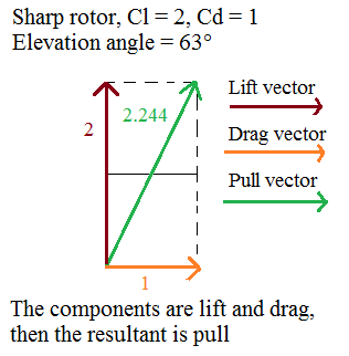
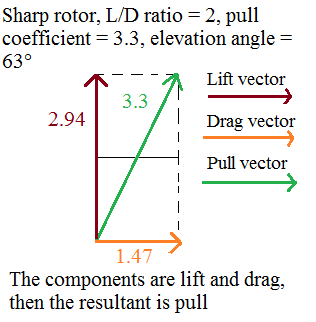
Peter Sharp is the inventor of this rotor which uses both Magnus and Kramer effect. The experiments I do confirm the lift to drag ratio of 2, that is a low value in absolute terms, but a high value for a self-rotating device like the one based on Savonius design with a lift to drag ratio of 1.
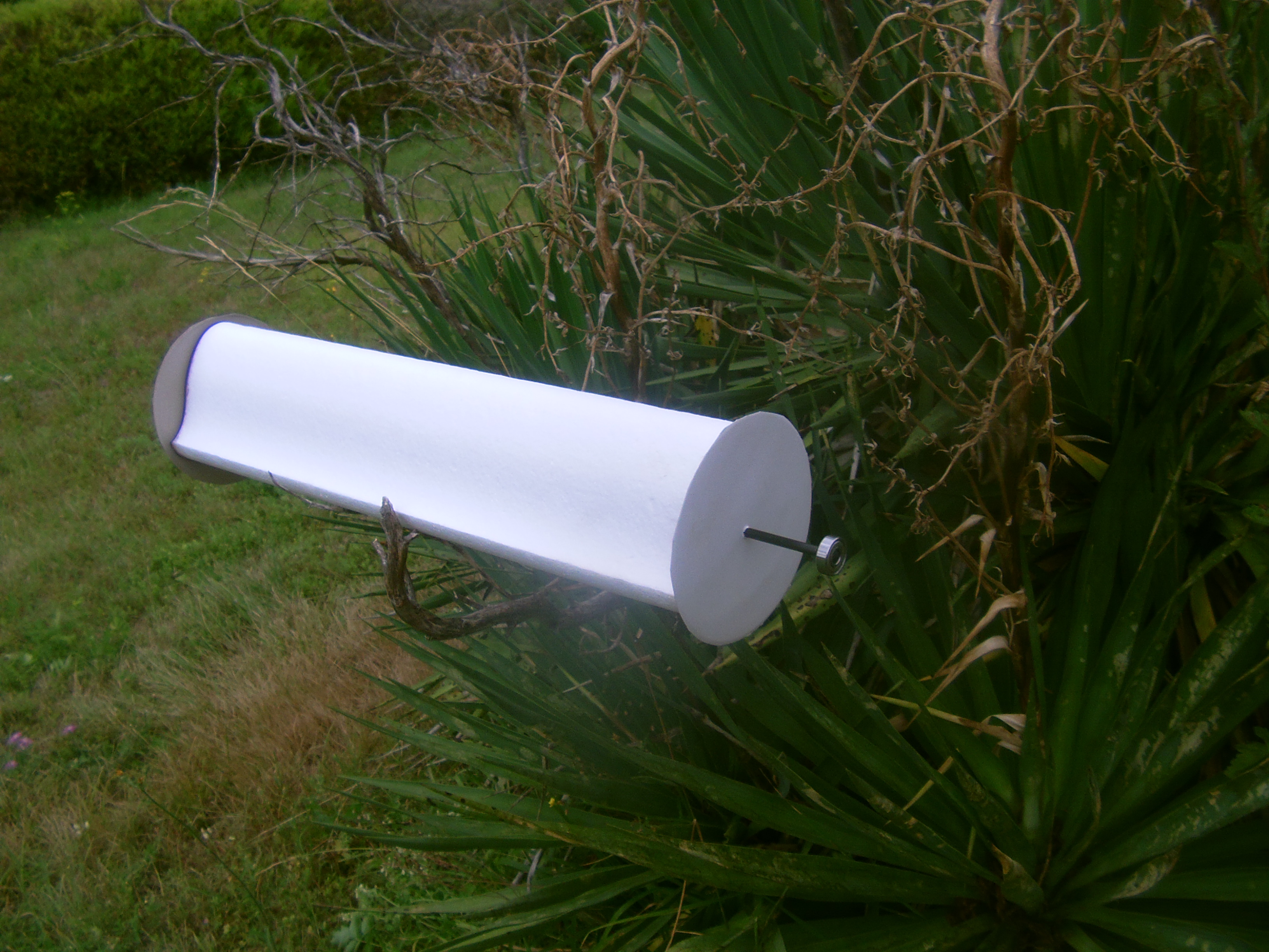
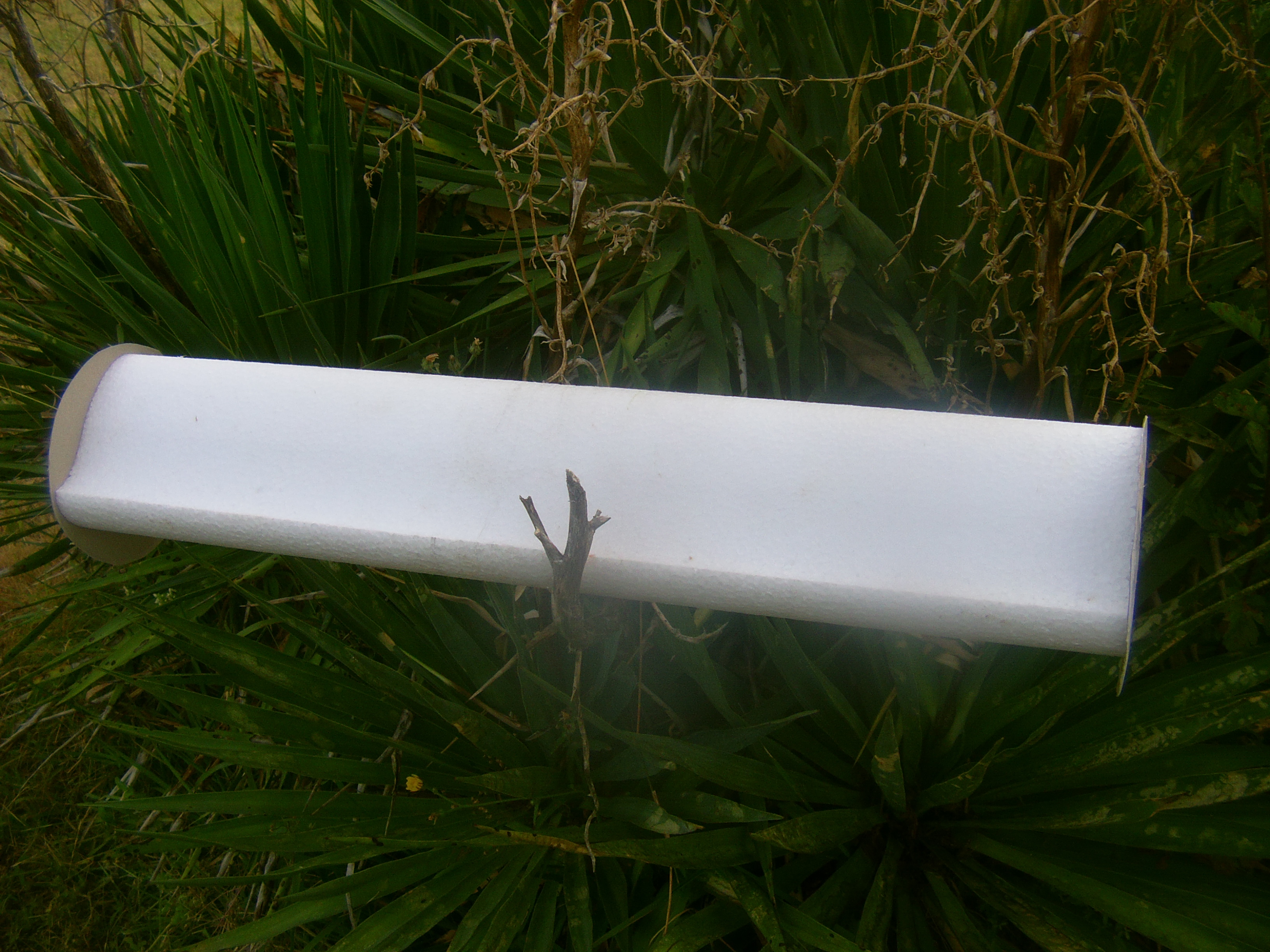
Foam prototypes were realized by using a cnc cutting machine and the profile below:
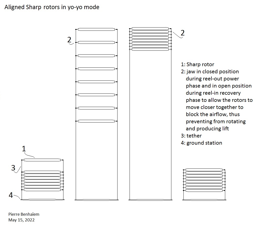
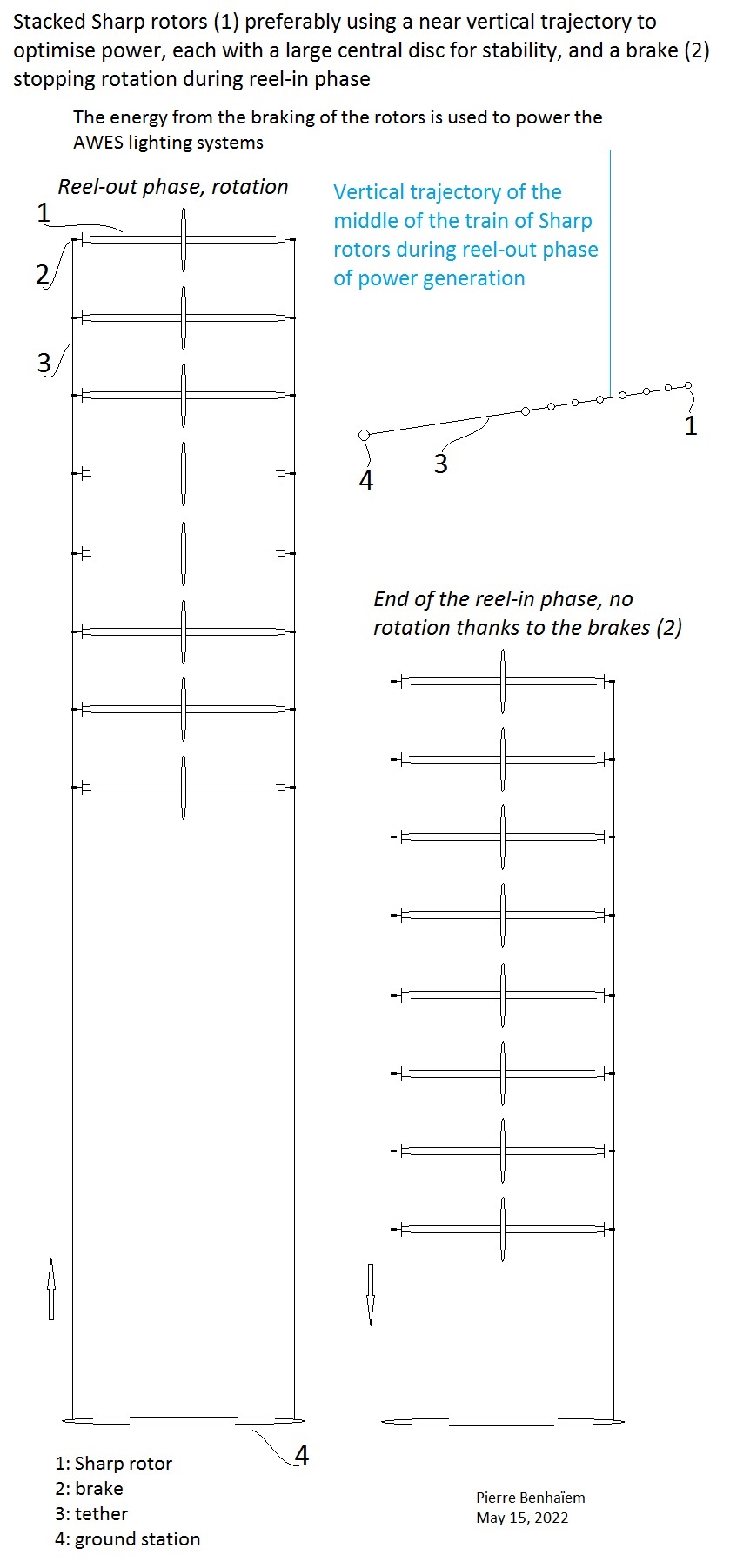
By my experiments and measures (see the videos above) and also some data from the inventor Peter Sharp about the Sharp rotor, the coefficient of pull could be between 2.2 and 3.3, involving in an average power of roughly 0.37 kW/m² for 1), 0.5 kW/m² for 2), and 0.6 kW/m² for 3), using yoyo mode and a vertical trajectory far from the winch as described in the chapter 13 (see at the end of the page) of AWEbook 2018. The three sketches are below:
During reel-out power phase it rotates. During reel-in phase it does not rotate, as for a Flettner rotor, but without spin motor.
Peter Sharp indicates that “A Sharp Rotor, due to its many curved surfaces, will be much stiffer than a cylinder”. So it could scale more than a Flettner-based balloon with the same holding by the two ends.
A solar balloon version would limit landing and take-off operations, without using helium.
As an inflatable version of the Sharp rotor would be highly scalable, as the unities within a farm could be close each other with low damages in the case of collisions, as the risk of collision is limited because the straight trajectory of each unity is easily manageable, the Sharp rotor could be an interesting AWE solution. Indeed the low efficiency per kite area is compensated by a better power/space use ratio.
By the experiments and some rough measures related above (coefficient of pull force at 12 m/s wind speed being 3.3, at 10 m/s wind speed being 3), and due to the huge power consumption of Flettner cylindrical balloons (which seems to be several times that of a rigid cylinder) as indicated on Scaling by size and on Scaling by size with a video, the Sharp rotor looks to be the more efficient device among Magnus effect-based balloons if the inflatable version keeps its features.
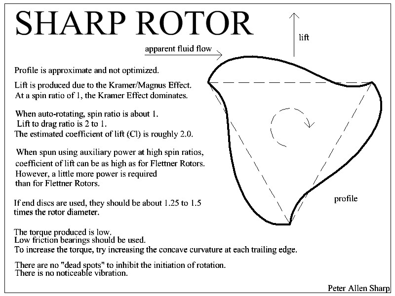
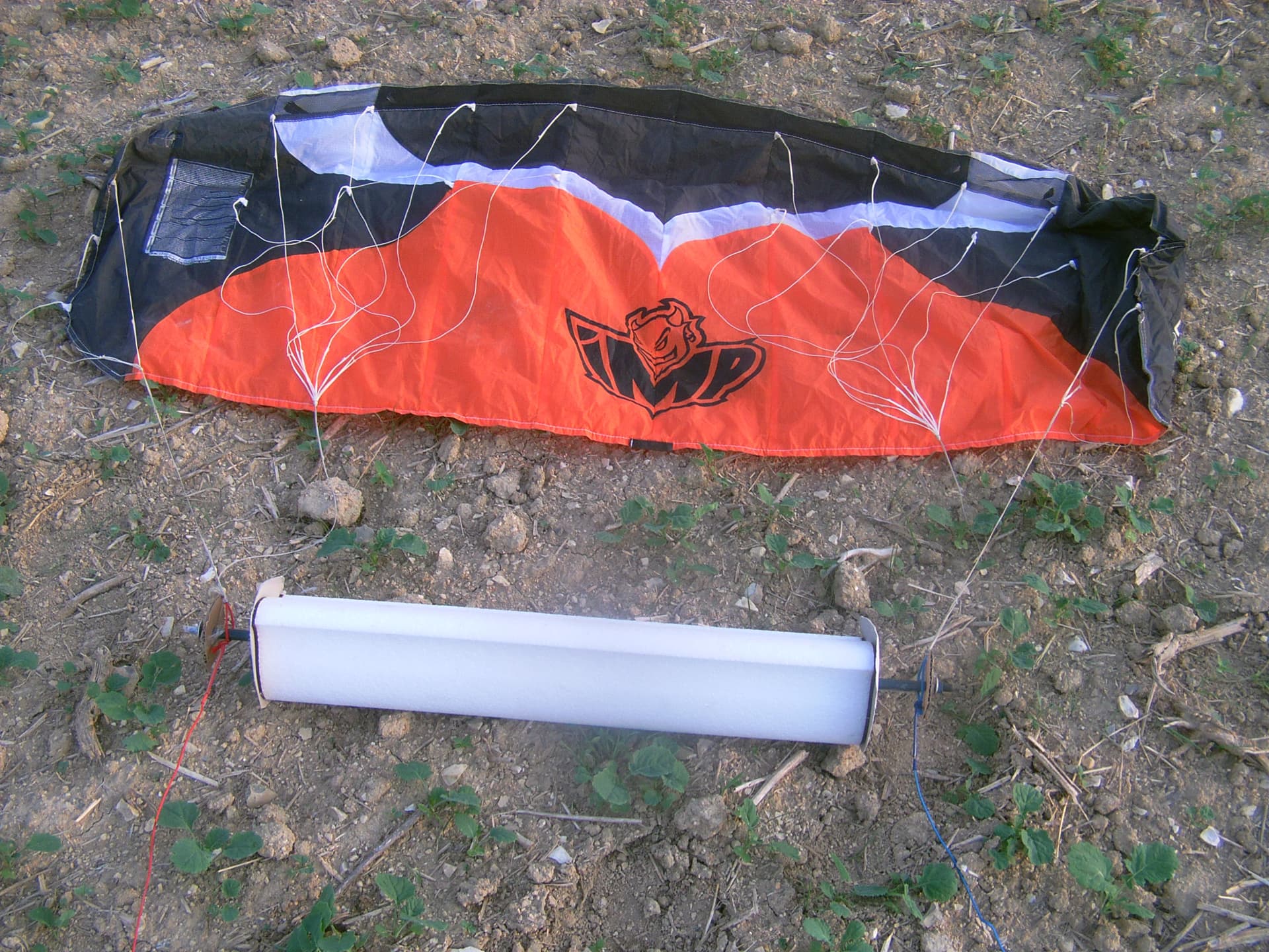
This is a presentation of the Sharp rotor. Peter A. Sharp (numerous inventions on https://www.youtube.com/channel/UChYQ…) is the inventor of this self-rotating rotor which generates a thrust with a lot of lift. This rotor can be easily made of paper according to the author, or EPP or expanded polystyrene like mine, with a hot wire cutting table, both by using the profile on https://forum.awesystems.info/t/sharp…. Larger inflatable versions filled with air or helium are also being studied.
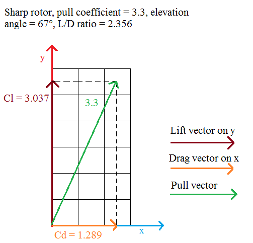
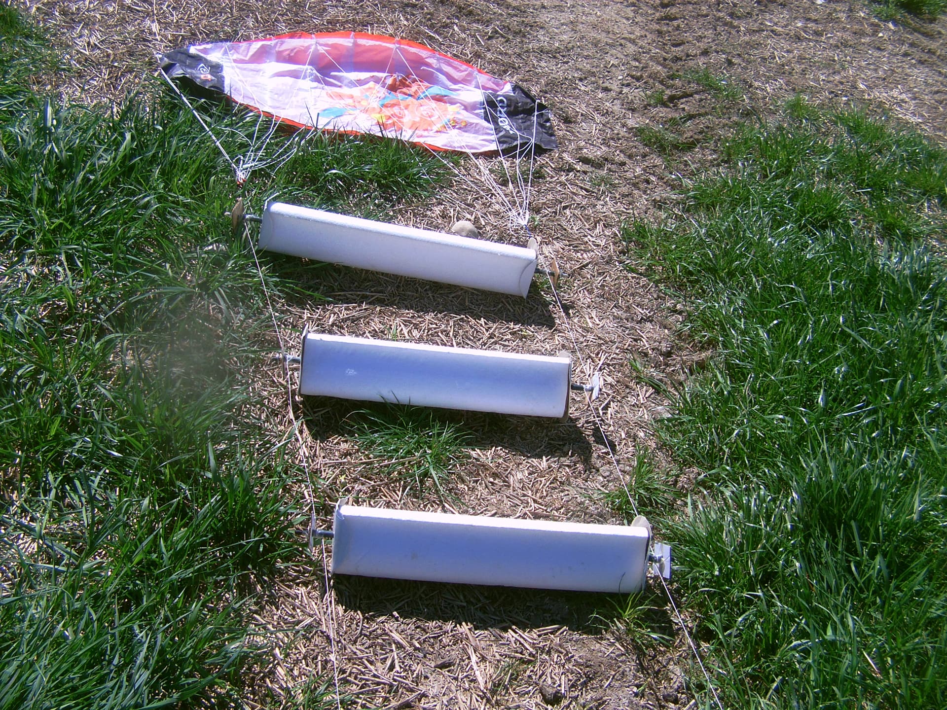
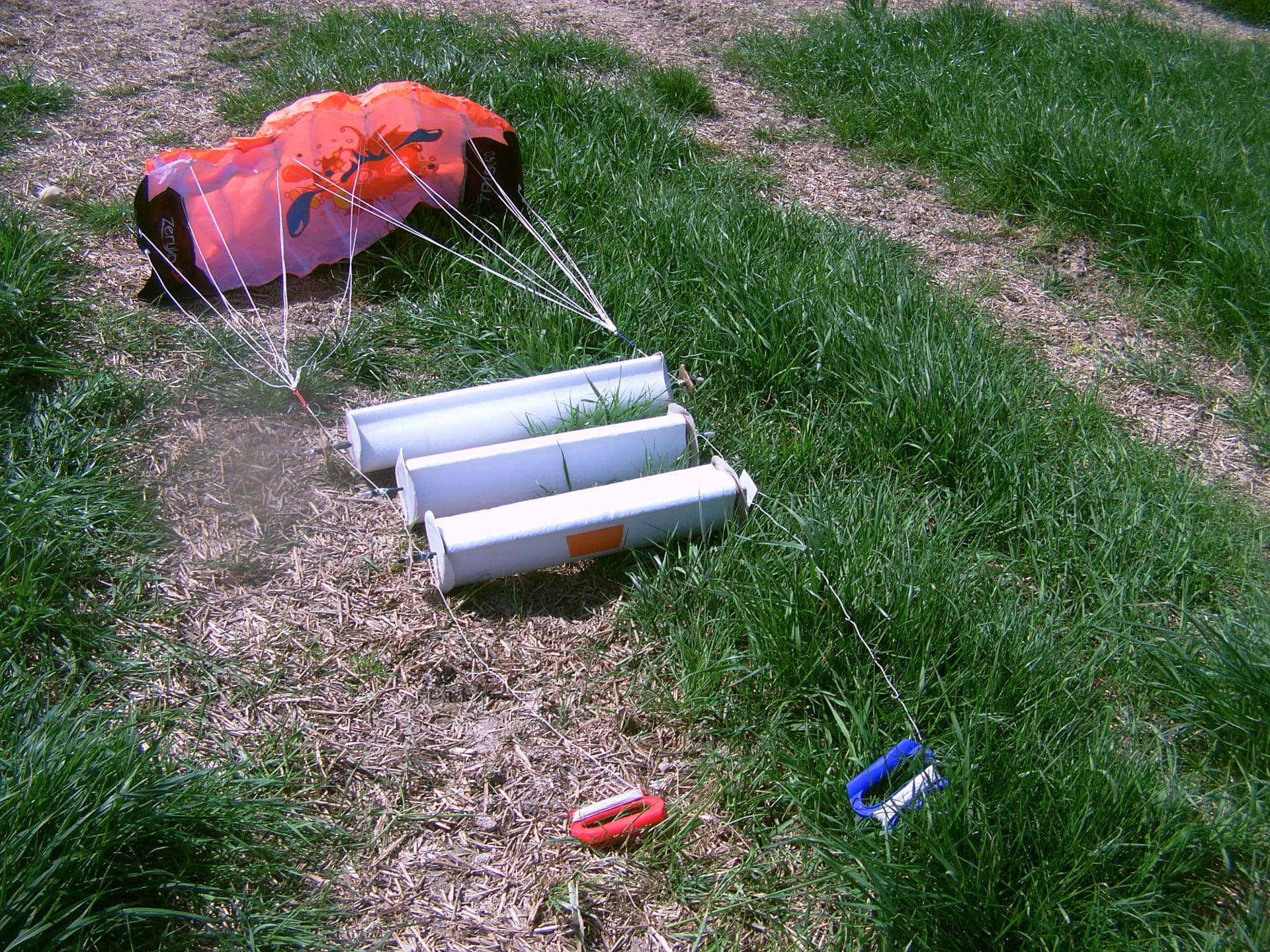
Its glide (lift to drag) ratio is given as 2, which is a very good value compared to other self-rotating rotors. My experiments even confirmed a bit higher value of about 2.3, with a thrust coefficient of about 3. The video shows the thrust measured during rotation at different wind speeds, followed by a glide test, followed by a Sharp rotor under a 0.9 m² kite, followed by three Sharp rotors covering only 0.175 m² in total under a 0.6 m² kite. The same kite alone flew about two times faster, generating two times less thrust that with the three rotors.10 m/s wind speed. Traction kite alone 4 kg. Traction rotors 8 kg + kite 1 kg, leading to a slow flight with strong pull (thrust).
An idea is to see if it is possible to stack a multitude of Sharp rotors under a crosswind kite between the two lines, like on the second part of the video but with many more rotors, in order to achieve a high level of scalability by using small elements that mitigate the weight penalty.
These rotors could be used for airborne wind energy systems (AWES) in yo-yo crosswind flight mode like sketched on the video, or also as sails for ships.
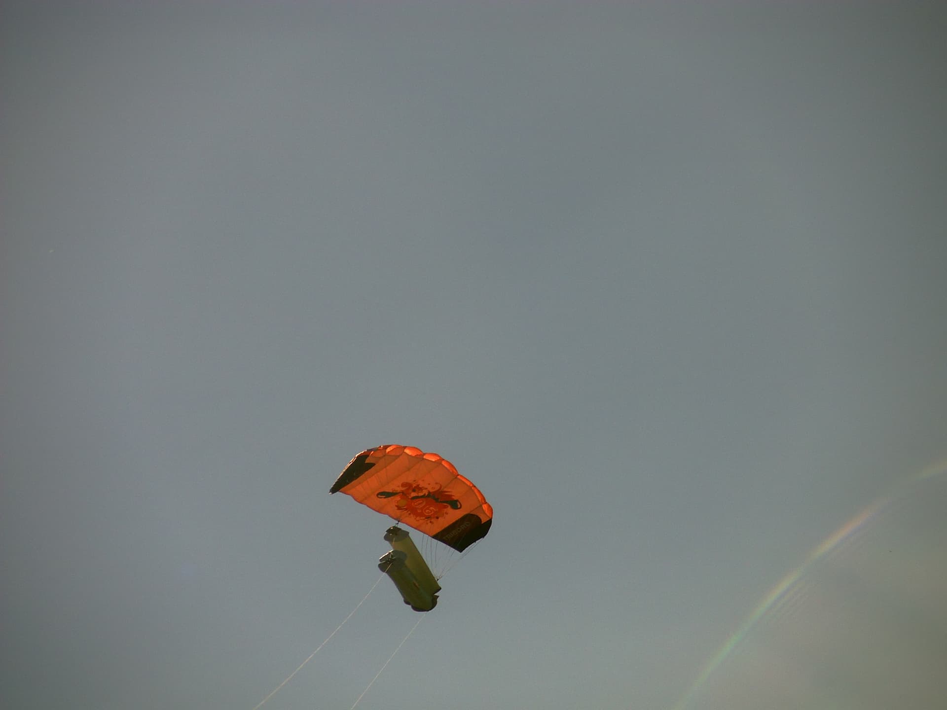
A photo of a Sharp rotor under a 0.9 m² kite, for a crosswind use:
Well done on the testing @PierreB
Great to see independent test data on Sharp rotors.
Impressed with how well the main kite was able to be controlled.
And you managed to film too. Bravo.
Did the Sharp rotors maintain alignment well?
Would they make steering harder?
Is your proposed power take off yo-yo or line driving or flygen?
Well done…! I was impressed to see this! I’m wondering if had a helix twist to it would it work better? Obviously this Is in a straight blade format. Grass cutting Lawn mower blades come to mind. If Consistent torque is needed? It could be something you could investigate? as the blade would have two point of contact with the incoming airflow along the length. Its also means a longer blade engagement with the airflow. If you made it with flexible rods and cloth? Could you variability adjust the blade profile? Essentially if you take the triple blade profile approach? Could you take it from straight blade to helical? By adding variable twits mechanism. Much like the flexible wing approach Ive seen on forum posts.
I was surprised myself. Filming this while piloting, while taking measures wit a steelyard, and with the sun in my eyes was not quite easy. But I have some information. The high thrust (pull = lift and drag) is confirmed. I would like to see if similar results can be obtained by putting rotors still closer each other.
Yes, because I put knots to stabilize their spacing. During turns they loss a bit the alignment, and loss also some rpm (listen the sometimes irregular noise on the video), then recover it.
The rotation system is far to be perfect: there is no ball-bearing during the flight, and also my ball-bearings used to measure thrust with high wind speed was replaced by simple sleeves that hit the axle at every turn, resulting in significant losses. Magnetic bearings would perhaps be a solution if they are light enough.
No, excepted for take-off that requires wind speed enough until the rotation occurs.
Yo-yo, because strong pull is produced. This is too slow for a flygen use.
Very well. I mentioned torque due to most motors when converted to generators. Need torque. I’d didn’t know if that something you were considering as part of the design?
Some experiments carried out today with a spacing of only 0.2m for Sharp rotors, instead of 0.41m.
Lower wind speed of 4-9 m/s. According to measures over very (too) short periods of time, it does not seem that bringing the rotors closer together has made them less efficient. It is a good new for scaling.
We have not heard from Peter Sharp in some time. It would be nice if he checked in or something. I was surprised when Peter first introduced his “Sharp Rotor” configuration.
To me, it looked like “just” a bloated Savonius rotor, with Savonius being the least efficient type of rotor commonly pursued.
Nonetheless, the big questions in my mind were:
Is Sharp Rotor an original idea in the first place? After all, it seems so simple, how could it not have been seen before, somewhere? I could imagine a food-mixing device, for example, or tires for going through a swamp, or just a fat version of a Savonius rotor. I’ve seen a lot of discussion in past years of modified Savonius rotors, including whether wind passing over the curved convex surfaces could provide “lift” at certain points in the rotation. I am still wondering if the idea is truly original, or if it has been used, pursued, or at least mentioned in the literature before. It resembles a cross-section of a drill bit, for example. Hard to imagine such a shape could have never been used before. Could such a shape have been used as an impeller or pump, for example?
But even if the shape has been used before, applying that shape to a wind energy rotor might be original. If so, I would say such a simple, yet original design for a wind energy rotor, is a major milestone in the art of wind turbine and fluid energy extraction. As to whether it ever finds a true use or catches on is another matter, but if original, I would say Peter deserves some serious credit for original thinking.
And the idea of a self-powered flettner or magnus type sail or “wing” is significant, since the reason flettner sails have not worked out has been they use more energy than they return.
So, on the one hand, you could say it is a solution in search of a problem, or an interesting device with no actual use case.
But on the other hand, if a configuration that simple has never been proposed or even envisioned before, that would indicate that, as advanced as we believe our mastery of aerodynamics to be, there might be very simple ideas out there that could totally change the field of aerodynamics, wind energy, aviation, fluid processing, etc.
Well I did find this wind-powered “Flettner” rotor ventilation fan (which I have seen before).
Supposedly they have been making these since the 1930’s, so a wind-powered “flettner” (Savonius?) rotor is apparently not a totally new idea. however the one shown seems to have two (2) lobes rather than three (3). Did this “flettner” company ever produce a 3-lobed version? Has anyone?
A Savonius rotor is designed to produce torque, while the Sharp rotor is designed to produce lift, and has a very low torque as the inventor specifies.
Peter Sharp indicated a lift to drag ratio of 2, which is a high value for a rotor. I experimented a bit rather higher value of about 2.3, with a pull coefficient of about 2.2-3.3, and a coefficient of lift of 2-3. The lift value of a Savonius rotor is far lower, being about 1, as for the drag value.
So I see a possibility for yo-yo (pull) use in (low speed) crosswind flight or in aligned mode, or as a lifter kite, perhaps a multitude of Sharp rotors as a networked giant lifter kite (for several Daisy systems?).
Yes compared to a flexible wing. I measured maximum values of about 2.5-3 for the coefficient of lift, and 3.3 for the coefficient of pull by using steelyards (see the video) with wind speeds of 10 m/s and 12 m/s of a 0.11 m diameter and 0.5 m span Sharp rotor.
No compared to High lift coefficient and biplane kite which can achieve a value of 3 or 4 with far less drag. But I think the management of Sharp rotors is easier and we can build some structures with them: they are like bars.
I put three 0.11 x 0.5 or 0.6 Sharp rotors with 0.2 m spacing under a kite: the pull was strong (60-70 N) if we take into account that the three rotors cover only 0.175 m², flying at about 20 m/s (wind speed 8-10 m/s), the pull of the kite being only about 10 N with the rotors, and 30 N (a low value, but I chose a low performance kite on purpose) when it flew alone. I have not see a major difference with 0.41 m spacing, video from 1:16. I confirmed this more or less today. But more accurate tests with different sizes of Sharp rotors would be required.
These experiments towards a flying hub around which the blades of an airborne wind turbine would rotate. The hub is intended to be very large and produce lift enough to allow the airborne wind turbine to fly in variously tilted positions but also in vertical position to maximize its efficiency. The wind speed was 6 to 11 m/s. Some lift was produced although the ring-Sharp rotors could be lighter, and the stability was not good during the brief periods of lift. Perhaps the stability can be better with helium inflated Sharp rotors, or with a lighter set, or by adding stabilizers.
My last experiments intend to see if blades could be installed around the ring-Sharp rotors which provides lift, avoiding a lifter kite.
Another sketch which is a lightly modified previously sketch:
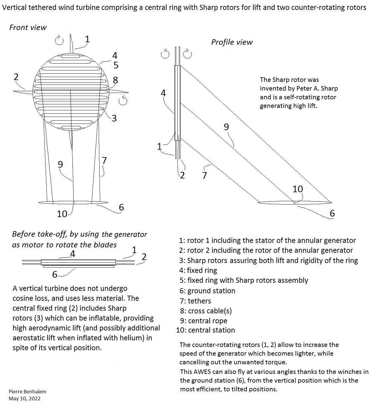
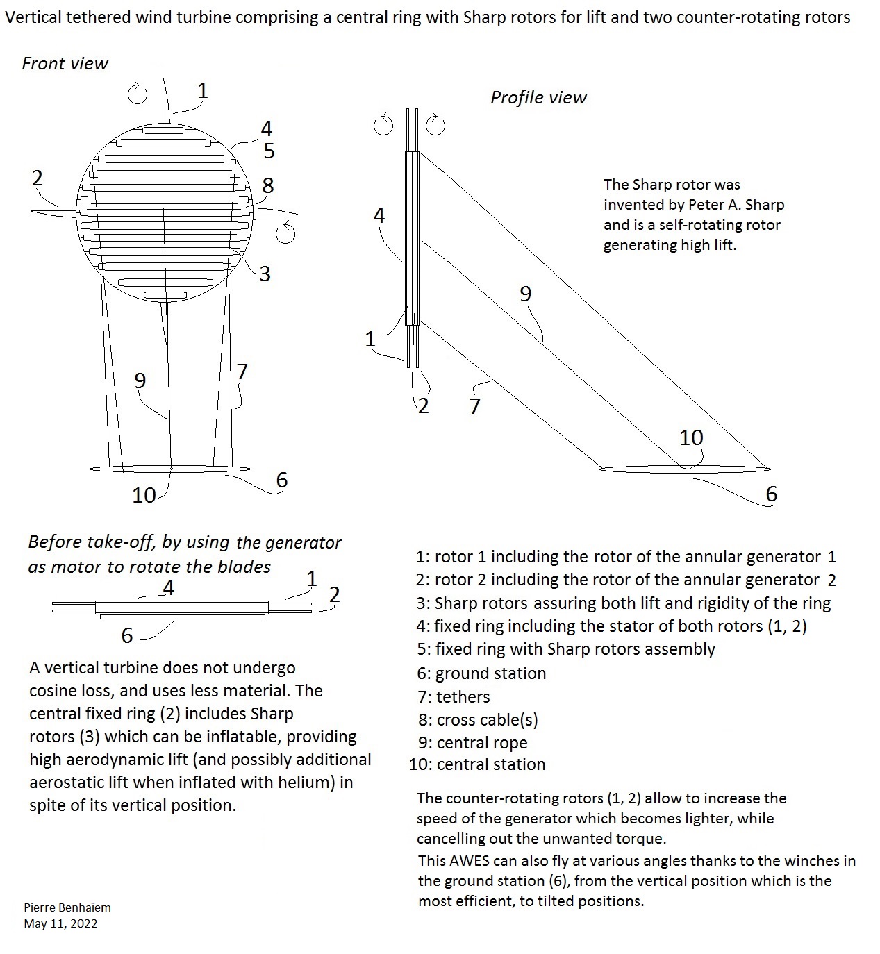
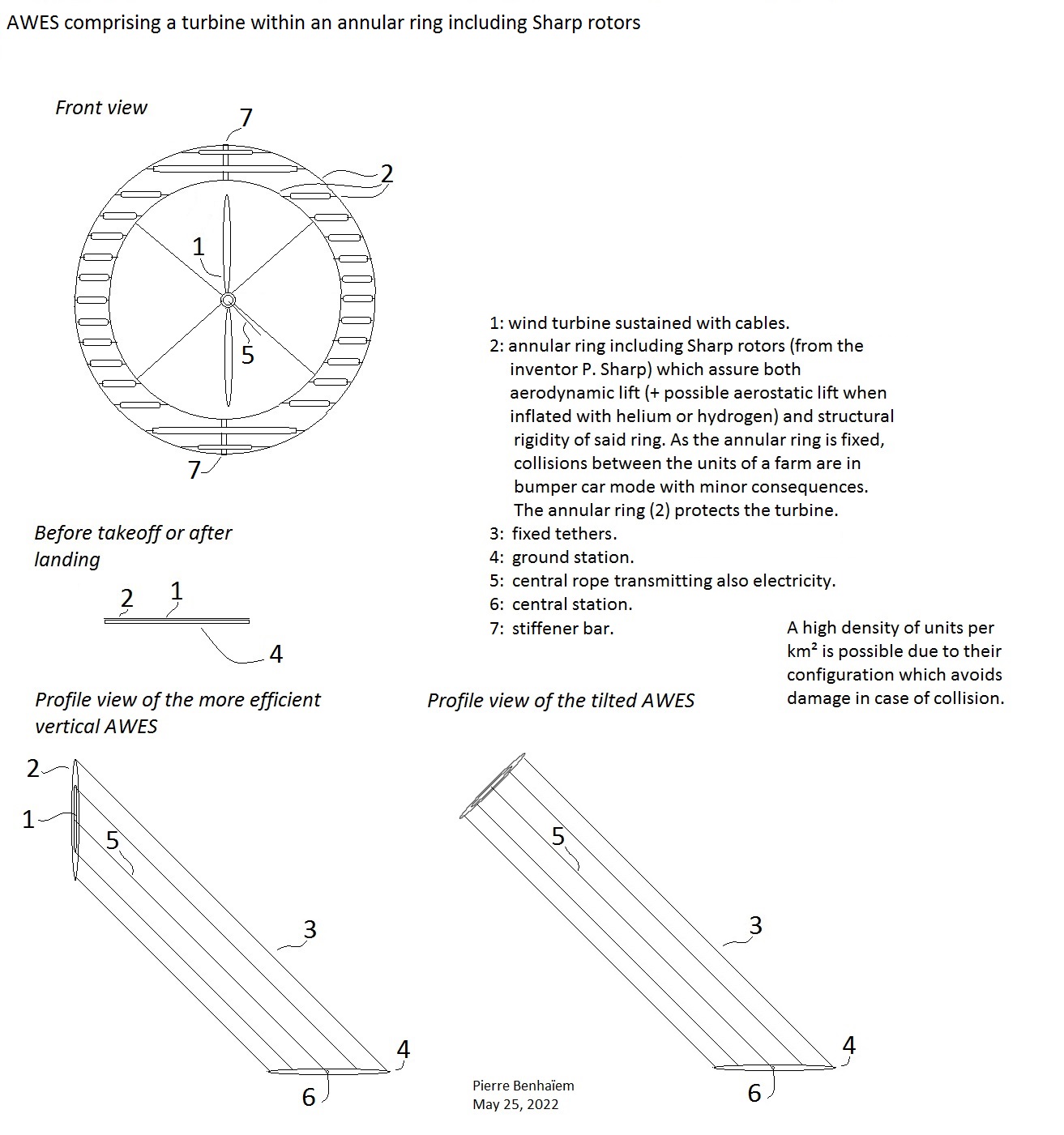
Continuing some investigations, this time with a fixed annular ring of Sharps rotors, again to provide lift and ensure some rigidity.
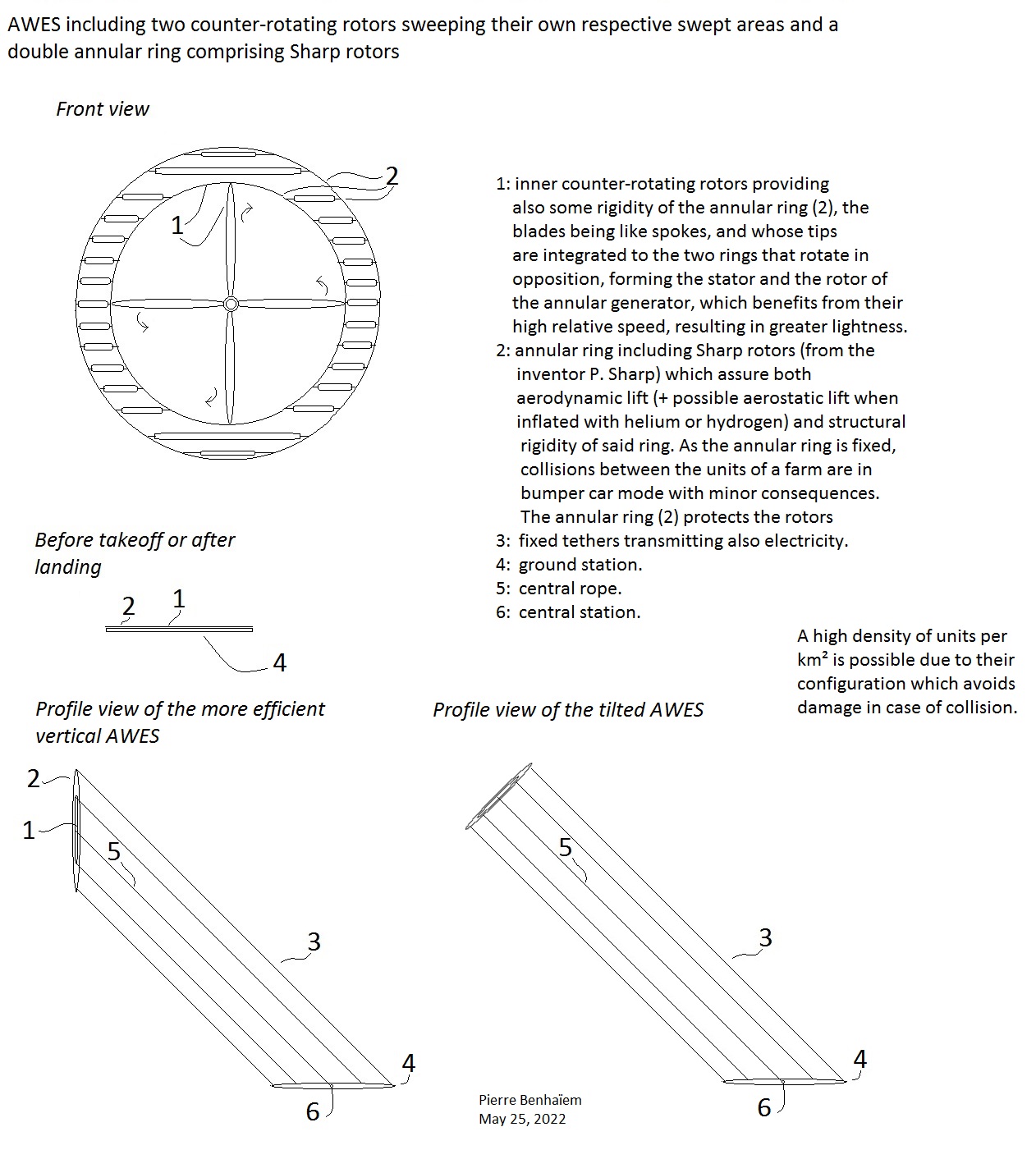
The two following sketches represent AWES whose the external part is the said ring, and could perhaps lead to denser farms of AWES, in some way in AWES farm in bumper car mode where collisions would have minor consequences due to the fixity of the external part. And also the tethers arranged in circular way prevent tangles between unities.
A turbine sustained by cables (Altaeros way) within the ring:
An inner rotor + an external rotor in such a way that each rotor sweeps its own area, the bumper car mode being not possible because of the external rotor:
The last is an example of an AWES with more potential of power by area, but a lesser Power to space use ratio because of the requirement of more spacing between unities within a farm.