Sharp rotor

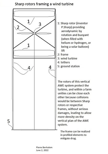
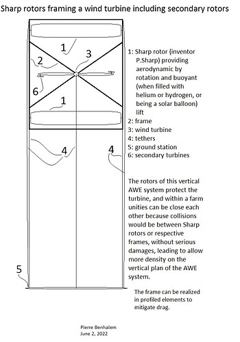
Maybe two simpler variants comprising a (vertical) wind turbine, then the same including secondary turbines, within a frame supporting large Sharp rotors:

In a farm, stacking in the height and width plane, the small vertical squares of AWES unities forming the large vertical square of the farm of AWES. The unities remain independent each other.

Apparently these people are working on Magnus based designs Experimental Validation on Using Drones for the Take-off and Landing Phases of an AWE System Zakeye Azaki, Grenoble-INP

1 Like

Hi Gordon, “no cosine cubed losses” is an argument among other arguments. Current wind turbines are more efficient than kites for electricity generation, it is all.

And also I sing several songs, including one from a lifter kite/balloon:

Indeed I think an inflatable Sharp rotor combines the qualities of a super lifter such as a high lift coefficient (see here), an ability to operate like an aerostat, and to scale a lot.

Yes. For many reasons, the Sharp rotor should be more investigated as a super lifter kite/balloon.

Sharp rotors could also work in AWES farm in bumper car mode - #4 by PierreB without significant risks of damages, protecting their respective wind turbines below.

Yes. As a result, a high elevation angle is a main feature for a high Power to space use ratio.

A simpler idea is using the stack of Sharp rotors under the kite as a static super lifter kite, what it was when I stopped it in flight. Stacking Sharp rotors between two lines seems easy and could lift a larger wind turbine aloft in fly-gen or rope drive transmission mode.

A lifter kite of 4 m² has a thrust (about 2/3 lift and 1/3 drag) equivalent to that of 3 Sharp rotors of 1.4 m x 0.35 m (counting only the aerodynamic thrust), at a rate of one rotor per meter. Indeed spacing 2 times the rotor diameter is sufficient for what I experimented. Assuming 300 rotors for 300 meters of lines, the thrust would be increased by 100 times.

The inventor Peter Sharp himself made paper rotors of 25 cm span.

I was intrigued by this rotor and, using the profile reproduced in the original post, had two 50 cm span polystyrene foam models made, and two 60 cm span EPP foam models.

The results of the experiments were even better than those predicted by the inventor. It is true that these rotors are larger and perhaps the material allows a more stable profile.

Perhaps the efficiency would be even better with much larger rotors leading to a higher Reynolds number.

The small models could be lightened by being hollow.

This rotor combines a high lift with the possibility of aerostatic use, while having a more or less straight configuration facilitating their stacking.

To my knowledge no one else has had the curiosity to build and test them, while there are a few Magnus balloon projects that depend on spin motors that consume all the more as the inflatable balloons hollow out during rapid rotations (spin ratio above 2 times the wind speed), while the spin ratio of the Sharp rotor is of the order of 1.

Pierre, please forgive me if this question is redundant, but how is the lift and drag of a Sharp rotor compared to a kytoon of similar material use?

Hi Doug,

Beyond its efficiency, it is its ease of installation in a stack that I find interesting.
That said I obtained as best measures a lift coefficient of 3 and a drag coefficient of 1.285 (see the third diagram of the vectors), leading to a lift to drag ratio of 2.33.

A good lifter kite has a similar lift to drag ratio, but far lower values of lift and drag coefficients (respectively about 1.2 at best and 0.5).

Values for a kytoon are that of a conventional airship (0.6 at best, figure 2), and of a kite.

So the lift coefficient of a Sharp rotor is far higher. Still higher lift coefficients are obtained with Magnus balloons that are rotating at a high spin ratio (2 and more), but it leads to high power consumption, above all with an inflatable balloon (see my previous message).

On the description Peter Sharp indicates that the “lift to drag ratio is 2 to 1”. He used a paper rotor of 25 cm span.

I obtained a glide number (lift to drag ratio) of about 2.33 (video at 0:33) with gliding tests, by using EPP foam 60 cm span and polystyrene foam 50 cm rotors.

Pull tests are reported in the beginning of the same video (0:10) by using a polystyrene foam 50 cm span rotor : thrust = 10 N at wind speed = 10 m/s, leading to a thrust (pull) coefficient of about 2.96; and thrust = 16 N at wind speed = 12 m/s, leading to a thrust (pull) coefficient of about 3.3. Friction losses due to the bearings may explain the lower values at lower wind speeds.

1 Like

According to the inventor peter Sharp, this rotor uses both Magnus and Kramer effect. I forget how the Kramer effect works. That said the Sharp rotor can be an inflatable rotor. I obtained foam rotors and tested them. I found a good lift coefficient of 2-3.

Higher lift coefficients (until 7 and perhaps more) can be achieved and were experimented for a Flettner rotor, as shown on the figure 4: https://www.sciencedirect.com/science/article/pii/S0167610518307396 , but the drag coefficient is high, so the lift to drag ratio is below 3, as for the Sharp rotor. See the power consumption on the figure 13.

I’m very impressed with your research experiments, Pierre.
I did find one reference to the Kramer effect regarding swimming.
Full article: Highlighting the Kramer effect in swimming (tandfonline.com)
I can’t say I understand it from a quick skim, with no diagrams to explain the Kramer effect.
But it does look like your flying sharp rotor is gliding like a wing.

5 The Kramer effect
In 1932 Max Kramer [8] performed wind tunnel experiments that were stimulated by the observations of some pilots that ‘gusty air was better than calm air’ as far as lift was concerned. Rapid changes in the incidence angle appeared to generate inexplicably high lift values, in clear contradiction to the Wagner effect. He therefore conceived an experiment which allowed him to simulate a sudden vertical gust in the wind tunnel and which confirmed the pilot observations. Rapid incidence angle changes produced lift values that exceeded the corresponding steady-state values. The effect was measured to be directly proportional to the rate of incidence angle change. Kramer postulated that the most probable explanation for this effect was the inertia of the flow separation process.

In the ensuing years this dynamic lift or stall effect has been studied in considerable detail, both
experimentally and computationally, because of its importance in the operation of flight vehicles
and wind turbines. For example, helicopter blades may fail due to exposure to dynamic stall. On
the other hand, fighter aircraft designers have tried to take advantage of dynamic lift to improve
fighter maneuverability.

The fundamental difference between the static and dynamic airfoil stall phenomena is shown
in Fig. 7 which is based on low-speed wind tunnel measurements by Carr et al. [9]. As already
found by Kramer, an airfoil that is pitched rapidly through the static stall angle produces a lift
much greater than the maximum observed at a steady angle of attack. Due to the delay in pressure
buildup, similar to the delay responsible for the Wagner effect, the boundary layer separation is
delayed on the suction surface and the lift continues to increase past the maximum static lift.
Eventually, flow reversal occurs in the boundary layer which is followed by the development of
a clockwise vortex near the leading edge. This vortex keeps growing and moving over the upper
airfoil surface, thereby inducing low pressures on this surface. As a result, a substantially larger
pressure difference between the lower and upper surfaces, and therefore a larger lift, is induced
than would be possible under static conditions. Therefore, for a short period of time lift values
that can be twice the static values are produced. However, this beneficial effect is lost as soon as
the dynamic stall vortex approaches the trailing edge. As seen in Fig. 7, the lift decreases abruptly
while, at the same time, a sharp pitching moment spike is induced. As the airfoil incidence is
reduced, the fully stalled flow over the suction surface starts to reattach. Hence the flow behavior
during the pitch-up and pitch-down strokes is quite different, leading to the hysteresis loops shown
in Fig. 7. This is further illustrated in Fig. 8 showing the suction surface pressure distributions
measured by McAlister et al. [10] on a NACA 0012 airfoil which is oscillated with an amplitude of
10◦ around a fixed angle of 15◦. Note the very large suction peaks near the leading edge followed
by an abrupt collapse of the leading edge suction.

These dynamic stall features can vary significantly, depending on airfoil shape, free-stream
Reynolds number and Mach number, and flow three-dimensionality. The prediction of dynamic stall has advanced considerably in recent years with the development of two- and three-dimensional
Navier–Stokes codes, but there are a number of flow phenomena that still defy currently available
computational methods, such as the prediction of the effect of transition from laminar to turbulent
flow, the prediction of flow reattachment, etc. For recent reviews of the physics and prediction of
dynamic stall we refer the reader to references [11, 12].

To be honest, I haven’t studied all that. But I did notice that the Sharp rotor seemed to have a higher lift coefficient as the wind speed increased, but maybe that was just an impression.

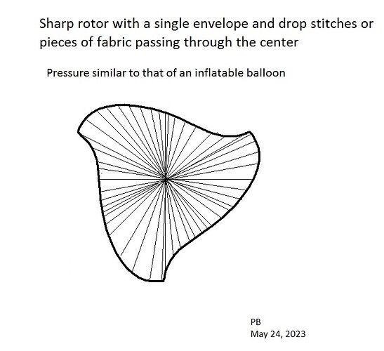
I’ve also considered (as has Peter Sharp) some inflatable versions. Here’s a sketch of something not easy to make, and whose shape is obtained by multiple diametrical walls of fabric:

Very interesting, Pierre.
Just goes to show us, things can be more complex than they appear.
I miss having Peter Sharp participating in our discussions - where is he?
Regarding using a Sharp rotor as a sail:
Please correct me if I’m wrong, but wouldn’t a flettner/magnus spinning sail be required to reverse its spin if the imcident wind switched from Starboard to Port (right to left)?
In other words, looking from above, if the incipient wind were coming from the left (port) side, the rotor would want to spin clockwise (to the right), and vice versa, correct?
So a Sharp rotor as a sail would be good for wind from one side, but not the other side, right? :slight_smile:

1 Like

We spoke recently by private email.

Yes.

Right. When the wind shifts to the other side, the Sharp rotor must be turned lengthwise, otherwise the thrust will be reversed. This is not practical. But with an AWES, you don’t have this problem: the rotor is horizontal and the whole thing moves with the ropes, like a Magnus balloon, well in theory.

1 Like

You know, it seems funny, but this is the first time, in all these years of discussing flettner/magnus sails for ships / boats, that it ever occurred to me that they would have to reverse the spin when the wind shifted. I do not believe I have ever heard anyone else mention it either. Seems like quite an omission of a pretty important, major requirement.

I would think that was obvious. The wind wont change that often. Changing the spin wont be very hard as they are motorized. Or, facing gusty wind from directly front, just stop the spin altogether.

Hi Tallak: Yes I agree it is obvious the moment you ask the question of which way it should rotate.
That;s why I think it is weird that:

  1. It had simply never occurred to me;
  2. I have never heard it mentioned, anywhere, ever - have you?

However, in a huge range on either side, it is “self-adjusting”. You’ve got a 180-degree range on each side with the same spin. And within that range, the “trim” of the “sail” is “automatic”?

I guess that is similar to having a STOL airplane with flettner/magnus powered, spinning “wings”, with no alierons, flaps, or way to adjust trim, aside from varying the spinning speed? How wouold you control it?

Do these ships need to keep adjusting the spin speed in response to wind direction to achieve proper “trim”? So does that mean they need to control the spin speed AND direction constantly in real time?

Anyway, to me, it boggles the mind that of all the “explanations” I’ve seen for these ships, I’ve NEVER seen ANY mention of the need to reverse the spin.

When you say it is "obvious, YES, it SHOULD BE obvious to people like US, who are supposedly thinking these things through, but for your average person, encountering the whole concept for the first time, it would NOT be obvious, since they are trying to take in the whole idea of whether such an unfamiliar concept could even work at all.

In my case, after so many years of fabricating blades and studying lift, even to the point that I’ve got the actua theory of lift everyone says is still unknown, I was so familiar with the flettner/magnus concept and the idea of “circulation”, that I simply accepted any picture or diagram of it working, without even thinking of what happens when the wind comes from the other direction.

Even the smartest of us has stupid moments! :slight_smile:

Anyway, this whole idea that no description or discussion of the flettner/magnus sails has ever mentioned something as basic as the need to reverse the direction of spin in response to the wind direction, is one more example of why we see so many whacky concepts funded and pursued, making great promises, only to fizzle out and disappear without ever achieving any of what was promised:
To me, it comes down to:
Single Factor Analysis
We are presented with a single factor, such as “A spinning cylinder can act as an airfoil, and thereby be used as a sail, a wing, or even a wind turbine blade”.

Based on such a single factor, promises are made, money is raised, people are hired, office space is rented, projects are announced, then… nothing.

In the case of the spinning cylinder sails, I’ve just flagged two (2) major points that have been “hidden” (by not being mentioned by the promoters). One may say they aren’t so important, but why aren’t they mentioned? Why don;t the “explanations” and explanatory videos mention the necessary change in spin direction?

When you look at the info presented by the promoters, they try to say their rotors are ten times as efficient as sails. I already explained how this was dishonest, using words to make something that might be unworkable in the long run, seem like some amazing breakthrough. Again, taking just the projected area rather than the total circumferential area of the sail, then ignoring the power required to run it, results in an “easy-to-understand” deception. You are presented with a single factor that is merely a strained interpretation based on word-abuse, and yet most people will just take it unquestioningly.

One might wonder, on the one hand, how experienced wind energy people like me and say, a Paul Gipe, could so easily and confidently declare an entire movement to revolutionize wind energy as bogus, with the thousands of people involved actually thinking they are “making a difference” or “creating the future”, while we laugh and point out how they don;t know what they are doing.

Well, it’s because we were already a decade or more into debunking wannabe-wind-energy-revolutionizing-concepts. It was a case of “been there, done that”. “Seen this movie before.”

But the question remains, how could so many people be so wrong? And I believe the answer is:
Single Factor Analysis.

Like with the kites puilling ships. Really, all one needs to know is someone is promoting an attempted improvement in the basic idea of wind energy, and you already know you;re looking at a 999/1000 failure rate.

It’s like looking at the crowd walking into a casino and asking what are the chances any of them will make a steady profit. Probably none. The house always wins. in wind energy, the wind always wins.

Anyway, I kept wondering what was holding back the kites-pulling-ships idea. What was the problem? For years I could not see why it was not working out, just that, as one more effort that always seemed to fizzle out, it “fit the pattern”. Then, the other day, I read or heard somewhere, that the ship had to travel 30% slower for the sail to be effective (If I even have that right). Apparently, reading between the lines, since we are seldom given the relevant information, if the ship is going too fast, it prevents a sail flying a pattern from having enough pull to make a difference. That is something I had never heard before. Another “hidden factor”, never mentioned in polite circles. We were never told that the ship ends up pulling the kite. We were presented with a single factor: A kite CAN pull a ship - without all the details of why it isn’t working out so well.

You can go on from one project to the next. Magenn - a single factor: This thing can fly and produce wind energy. But the other factors were it’s the least effective form of wind turbine, made a hundred times as expensive.

Altaeros: A tubular balloon can lift a wind turbine that can make some power. A single factor. nevermind that it’s too fragile to withstand a decent wind, or that the tube eliminates most of lifting volume.

Makani: A single factor: A wing can move a wind turbine through the air faster than the wind speed. But the fact that it could barely fly a pattern at all was not mentioned. The real story is they must have been glad when they lost their single overpriced large prototype so they finally had an excuse to “just give up”. If it had been promising, no single crash would have discouraged them. meanwhile, why was the whole world thinking they were about to revolutionize wind energy? They only got a single factor to examine (a wing can push a turbine faster than the wind), not all the nitty-gritty details that suggested it might not be so great.

Anyway, the funny thing is, you can’t tell people they are idiots, because if they could understand they were idiots, they wouldn’t be idiots. And by hiding all the relevant facts, presenting only a single factor, idiots can find other idiots to fund them, and magazines and websited to repeat their single-factor presentations, and so the whole thing goes on - laughable for a few, puzzling for the many.

I’ve noticed this in life in general - every time you are presented with some supposedly urgent issue or problem, ask yourself if you are being shown only a single factor. Ask about all the othr factors they are not addressing. Ask questions and look at the situation from every angle, and maybe you can debunk something yourself. :slight_smile:

I guess. But an anemometer on the ship should give a good reading of the wind and then rotate at a speed close to theoretical. Quite simple. I dont think it need to be super precise.

Actually, spin speed is adjusted relative to wind speed. Direction only changes when going from wind port to stbd.

Compare that to a wing where you need to orient it at an accuracy of a few, maybe less, degrees for good performance. And really difficult to measure accurately.

Its night and day

Yes, well I was just citing an example of single-factor analysis. And noting how it seems to happen in every case.
All the details, or why a regular sail is “worse”, are interesting, but beside my point.
My point is just that if we are only presented with a single factor to analyze, and don’t take it further, that might explain the “million flies” phenomenon.

It may also help explain “group-think”, where “everyone is wrong together” becuase there is only a single viewpoint that is even considered worthy of discussion, and any deviation is considered heresy, and stamped out. No thinking allowed. Only bumper-sticker level reasoning, only considering one single factor. But no factor exists in a vacuum. There are always more factors to consider. :slight_smile:

For this reason scientific people like to stick to precise physical wordings and may be fuzzy about them used in a wrong way.

I was mentally continuing a discussion where I stated that a magnus sail was easier to implement than a airfoil based sail. It is just discussing a single aspect of the design. I think doing so is fair in this forum. It should be clear that this is not a complete comparatively analysis.

But, to do a multi factor analysis, I think I like the magnus sail better than a foil based one, for shipping. Some arguments:

  • easier to control revolution speed than sheeting a sail, automatically
  • robust construction lasting for many years
  • simple actuation
  • small size
  • size and construction may mean they can be deployed in high winds.

Now there are some unanswered considerations that must be accounted for;

  • will magnus sails offer a lift to drag ratio that is useful in the winds the ship encounter, and at the vessel’s required travel speed [l/d ratio and direction of apparent wind, and a sizeable portion of wing lift must point in direction of travel]
  • power input requirements
  • actual fuel savings [a number 8% means little unless you also state under which circumstances etc]