Yes, there are a few possible compelling reasons why the spinning cylinder could make a good sail, I guess. One factor I wonder about is safety in storms. That’s a lot of surface area, with good leverage to capsize the boat. Maybe Pierre is right - use a Sharp rotor. It needs to be flipped over if the wind shifts.
Whatever you use to flip it over might also be used to lay it down in a storm. And it needs no drive mechanism, and uses no power.
I expect a solution with a hinge on the base and maybe a crane already onboard could be sufficient if one needs to lay down the sail during a storm.
The sharp rotor needs to be flipped which seems to require complex operations.
I think if you went for the sharp rotor, a moveable flap system would be easier to implement to make it rotate in either direction. I dont have ant specific design in mind but I think it should be feasible.
For me I dont know enough about the sharp rotor to comment on usefullness in this application, in particular the glide number vs the magnus sail. But losing the motor does seem attractive. Has anyone done research on this?
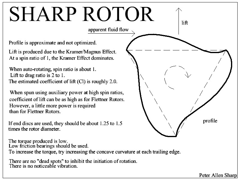
Peter Allen Sharp indicates 2. I measured 2.3, so a value comparable to that of a Flettner rotor. At 12 m/s wind speed I measured a pull (thrust) coefficient of about 3.3 (see the numbers on the video), and a lift coefficient of 3, although my measures were not very precise due to incessant wind changes in intensity.
A Flettner rotor can achieve a far higher lift coefficient (about 7 for a spin ratio of 4) but the power consumption increases by the cube of the tangential speed of rotation. If wind speed is low, it is OK, but if the wind speed is something like 15 m/s, the tangential speed will be 60 m/s, leading to a huge power consumption.
The Flettner rotor benefits from the two directions of rotation.
The implementation of a Sharp rotor can be easier since there is no need for a motor and for its rotation transmission; it spins freely. In the other hand the shape can be more difficult to achieve.
The lift to drag ratio is of great importance for a ship travelling fast. Without that, its impossible to gauge how well this could work
The lift to drag ratio is 2 or 2.3 for a Sharp rotor, and about 2.64 for a Flettner rotor with a lift coefficient of 7 by a spin ratio of 4 (Fig. 4), and a drag coefficient of about 2.65 by the same spin ratio of 4 (Fig. 7). These coefficients are not very high.
An excerpt:
The potential of a Flettner rotor to reduce a vessel’s fuel consumption is already well established. However, the rotor is also known to have a relatively large drag, which reduces its aerodynamic efficiency, particularly when sailing upwind.
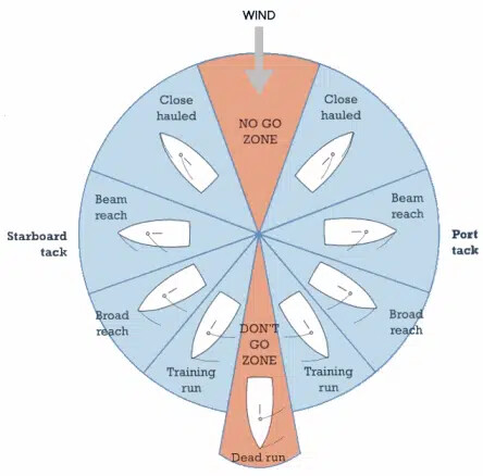
I’m not sure that you can have as many points of sailing as with a conventional sail (see sketch below).
Thanks for providing info on this. Organizing such info seems to be a special talent for you @PierreB and a special weakness for me.
Anyways. With those numbers I would look elsewhere for propulsion. The magnus/sharp sail would be pulling mostly sideways relative to the ship direction of travel, except in especially beneficial conditions (strong wind, slow ship speed, good direction of wind)
Example: wind and ship speed equal, wind perpendicular to path of travel. Sail l/d is 2.
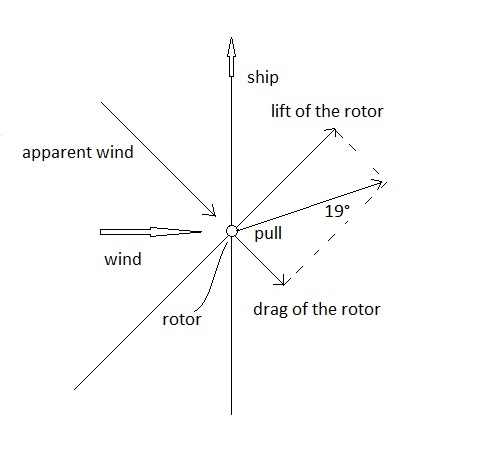
Apparent wind is 45 degree downwind. Sail has an angle to the apparent wind 64 degrees. The kite is pulling mostly sideways with a forwards angle of 19 degrees. So if the pull of the sail is 10 kN [~ 1 ton], only 320 kg forward pull.
At the moment the ship speed to wind speed ratio equals the l/d ratio, the sail is pulling just sideways.
But there are other things to consider as well. Power expenditure was mentioned. The keel maybe has a l/d of 4, which means that 9.4 kN sideways pull generates 2.4 kN drag subsea. That leaves just 0.8 kN net propulsion in the example above.
Like always, a fascinating idea death by a thousand cuts.
Note this is a very quick estimate it may not be correct…
Speaking of things that seem obvious, it seems obvious to me that a trailing flap could improve performance of a flettner rotor. I’ve always wondered why STOL attempts using a flettner wing did not include flaps, and maybe slats. Just the additional chord (more surface area) should increase performance, let alone the ability to “aim” (if the flap is adjustable) or redirect air backwards, if aimed backwards.
One factor I had not really considered was the extra drag from the sail when not in use, or when traveling upwind. Like Tallak said, “death by 1000 cuts”!
Other problems are said to include those caused by the spin of the rotor - while they are not specific, I’m guessing oscillation and vibration?
By the time we’re adding a flap - if it is adjustable, we’re back to aiming, as with a sail, negating the stated advantage of the flettner to not require aim.
This is starting to remind me of vertical-axis wind turbines.
They start out saying their advantage is “no need to aim”.
The very next thing is they say “but we can enhance performance if we adjust the blade pitch cyclically in response to the wind direction.”
So much for “no need to aim”.
Since “no need to aim” was the only advantage the vertical-axis machine allegedly had, throwing that advantage away means you should have just used a regular wind turbine.
At that point, the only reason one could still want to pursue a vertical-axis design is being in love with the vertical-axis idea.
It’s like falling on love with a prostitute - “All I’ve gotta do is get her to stop selling her body and everything will be great!”.
Same with so many of these concepts:
“All ya gotta do is…”
All ya gotta do is spin a cylinder!
(But then the spin itself causes problems)
All ya gotta do is add flaps!
(but then the flaps need to be aimed in real time)
On and on it goes.
Take what could possibly be one of the simplest machines ever conceived, and keep making it more complicated, using more material, more and more “all-ya-gotta-do-is” modifications, until you have something that increases cost, weight, safety hazards, drag, structural and operational complication, reduces cargo area, on and on - Tallak said it best - death by 1000 cuts~! ![]()
Indeed Tan(about 64 degrees) is 2 since L/D ratio is 2. A sketch showing this forwards angle of 19 degrees, hoping there is something right:
That’s not very encouraging.
A simple idea: the rotational power of the Flettner rotors is allocated to the main power-train, with the rotors removed. So no change.
The problem with sails or kites of any kind is that they impose forces that impede the forward movement of the ship, and against which the main engine has to fight, resulting in increased fuel consumption.
Placing this 19 deg fore or aft on the deck will get a different response from the hull of the ship.
Thinking like a windsurfer.
The overall overall hull form must have some lift response
OK you’re not going to get it planing or up on hydrofoils but
Surely (question) with even a pure sideways force the hull will induce a component of forward motion.
Sorry for turning up late to the chat
1 Like
I think not, because then you are not travelling in the same direction anymore. You need some sideways slip. So that just means heading a little downwind.
I think its a matter of selecting a reference frame.
I am not 100% sure though. I would need to give it more thought.
Such a force diagram adds to the little details that make ideas that sound great at first, turn out to be not-so-great.
I’ve been impressed with the Sharp rotor from day-one though.
To me, it looks as though you took a Savonius rotor and covered it with shrink warp, then applied heat to shrink the covering around the Savonius rotor.
It is so simple, yet nobody has really explored it much at all.
To me, it is an example of:
- simple configurations that remain largely unexplored
- the general level of mental and creative helplessness that tends to afflict us as humans
- The number of simple devices, like “the wheel” or “fired clay pottery”, staring us in the face, as we proceed on like ancient civilizations that had no wheel. no pottery, etc. even though nobody was stopping anyone from developing.
Did you know archaeological digs from 8000 years ago in Turkey reveal no pottery, let alone wheels?
But peoples’ brains were bigger…
But now we’re “domesticated.”
Did you know wolves have bigger brains than domesticated dogs?
Maybe this explains the Fermi paradox: as a civilization gains knowledge, the individuals lose the need for intelligence to survive.
What I didn’t mention is my long established belief that any sail or kite that is to be useful for modern shipping must have a L/D ratio of more than 4. Preferably more than 10 and then moving about.
This implies to a great deal that I believe kites like eg. Skysails are promoting are doomed to niche markets. And any successful ship AWE would probably be looking like a solid airfoil.
And also such a ship would need an efficient keel. I expect for such a large ship as a cargo ship we may be looking at many smaller keels so to keep the aspect ratio of the keel high without going monstrously deep. I am not sure how the rest of the hull though would interact with such keels.
In the end, maybe we dont need to think so much about the shape of the AWE or sail; it may already be unviable just looking at the keel/hull and practical water depth
As a kite during a few seconds:

1 Like
Also, don’t forget about stuff like seaweed and fishing tackle getting caught by any structure dangling or extending directly down into the water, especially if not slanted backwards.
1 Like
The shape of an inflatable Sharp rotor could surely be ensured by using shapewave® technology, and perhaps at any dimensions.
LIGHTWEIGHT
shapewave® technology uses coated fabrics available airtight from the roll, for use in constructions from ultra light to heavy duty. Each of the thousands of webs inside your shapewave® inflatable is precision calculated in accordance with physics laws by our WAM software for an optimised construction.
Our ultralight proprietary tape material hardly adds to the construction weight. Weight savings of over 60% compared to traditional inflatable tech are within reach. At the lightest of light, we’re looking at construction weights south of 100gr/m² for ram-air canopies.
FREEDOM OF SHAPE
Liberate your designs from tubular, flat panel or box confinement as you tap in to the world of shapewave®! Double curvature, sharp edges*, convex or concave, our proprietary WAM software will fill your design out with the required tape density, while providing panel join lines to build the inflatable parts you’ve been dreaming of.
*Current minimum radius is R18mm. Note that thin sections of inflatables can become “soft” due to reduced hoop stress. Blame physics! However, sharper edges can be achieved by other means, please contact us for details.
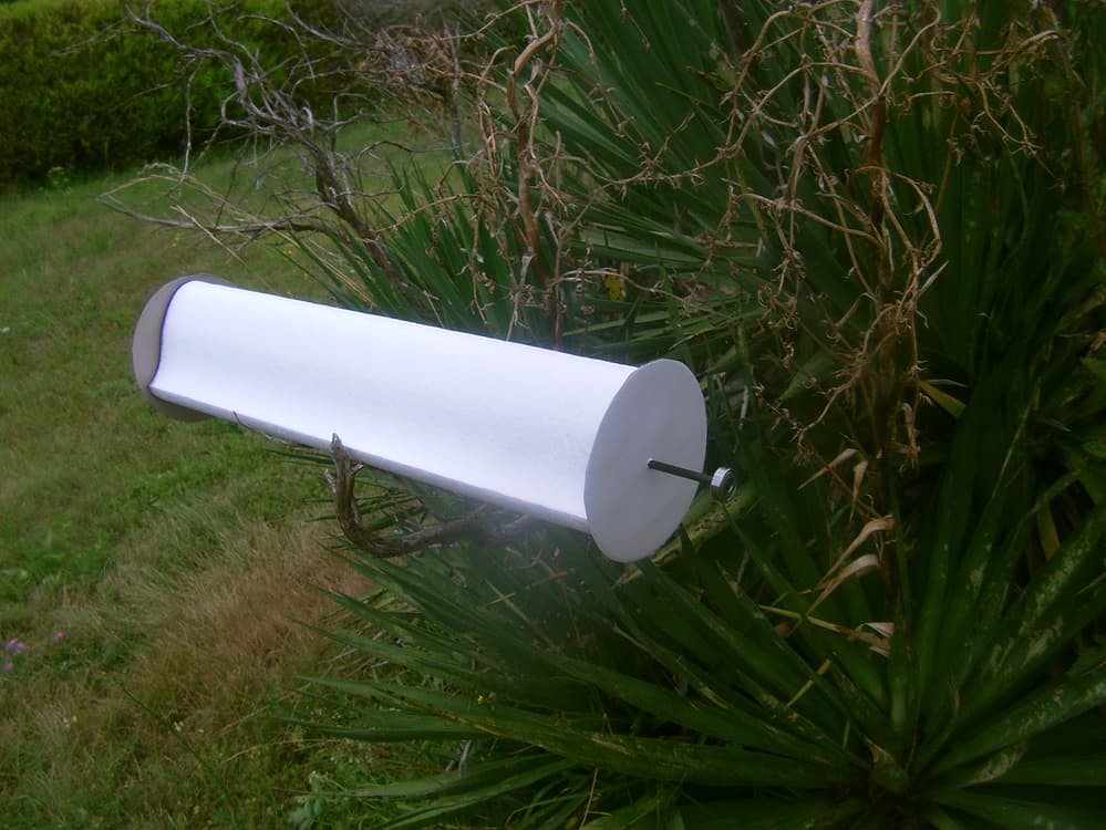
I tested (see the video) of this self-rotating rotor with a high coefficient of lift (close to 3).
With this technology it could be build at good dimensions compared to my limited foam rotors, perhaps at high scale. What do you think @Rudo ?
Hi Pierre,
thank you for considering shapewave for this cool project. I’m sure we can build something inflatable in this shape, we probably need to build 3 more or less flat sections and weld them together, so the thing would be double walled. I guess the sharp edge needs to be precisely shaped, we may need to use some semi flexible stiffeners (cut from sheet) in there, or battens.
I wish I could spend time on this but our focus now is to get the wavemaker01 up and running!
I may try some doodling and post the results on here.
3 Likes
Hi Rudo,
Thank you for these explanations which are more than sufficient to have an idea of the feasibility.
Wishing you success with this very promising technology.
I am only a hobbyist. For the moment I do not have a specific project on this rotor that I had started to test, and of which I am not the inventor, who is Peter Sharp with whom I am in contact. I will forward your response to Peter.
Thank you very much, but there’s no rush.
I also provide again the profile of this rotor, then a complete small foam rotor, for a possible discussion on the forum.
I had tried to figured an inflatable rotor (see below), but it is only a preliminary sketch, and perhaps it does not lead to something feasible.
aren’t we all
your sketch is interesting, not sure if it works like that physically. I’d say the webs in the concave “hook” section won’t behave as drawn, a portion may flip and become convex.
Anyway you planted it in my head now - no way it will be at rest there!
2 Likes
Sharp rotor of which rpm is aligned with VAWT, leading to no moving piece relative to another:
A single unity including a VAWT + a Sharp rotor + a VAWT + a Sharp rotor + a VAWT and so on, or a Sharp rotor + a VAWT + a Sharp rotor (and so on), is perhaps easier for managing than a stack of unities.
The Sharp rotors could be replaced with Flettner rotors (simple cylinders) that are rotated by the VAWT.
2 Likes
Wow Pierre, you never stop thinking.
Nice idea!
![]()
1 Like