A (train of) parasail(s) as AWES ?

It is reasonable to think that the same would be true for parasails: decrease in Cd when wind speed increases. In any case, this is what a research group tried to demonstrate:

https://eng-web1.eng.famu.fsu.edu/me/senior_design/2007/team4/Analysis_&_Results.html

The parasail was found to have a drag coefficient of slightly less than the estimated value. The textbook drag coefficient for a parachute is about 1.3 while the test showed a drag coefficient of approximately 1.2 for the two out three most accurate tests. The drag coefficient was very high at 1.7 for the 90 lb test weight. A likely reason for this is that the drag coefficient seemed to decrease as wind speed increased. The wind speeds for the 90 lb test included values of below 10 mph with abnormally high tension readings. These raised the value for the average drag oefficient. These results could be erroneous due to bad recording conditions but it is also possible that the behavior of the parasail is not as predicted in the theoretical calculations. If the drag coefficient of the parasail does in fact decrease with an increase in wind velocity, this could be very beneficial for the safety of the entire system. A dangerous high velocity gust would have a lesser effect than what was previously expected. For the purpose of safety, however, it will be assumed that the drag coefficient will not decrease below the value recorded at our maximum test speed of 25 miles per hour.

The wind speeds for the 90 lb test included values of below 10 mph”, so comparable to the sink rate of rescue parachutes. This looks to confirm that at wind speed of 10 m/s or more, the drag coefficient (Cd) would be lower (in this excerpt, a Cd of 1.2 is noted).

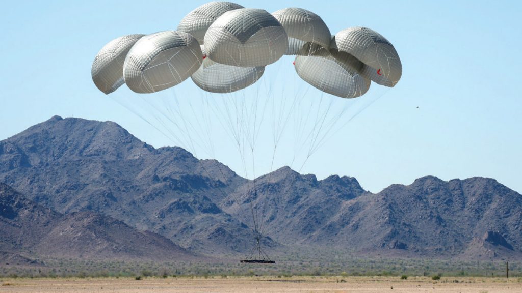
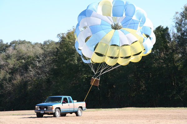
A representative photo of tests on Eglin 4 - FSU ME Senior Design Project :
Agonizing to keep reading through this endless microscopic analysis of parachute minutiae. If anyone wanted to build a hopefully-useful machine employing parachutes to make electricity, it could be easily done at a small scale. If it then proved useful for any purpose, one might start optimizing the type of parachutes, etc. Meanwhile, it amounts to rearranging the deck chairs on a mythical Titanic that has not even a blueprint, let alone being built, let alone being launched, let alone sailing,

Basically, just like any reeling AWES, it’s a question of force (in N) x 1/3 wind speed (to simplify).

Electricity has already been produced with parachutes. Which I will not do again. I started by measuring the force of a simple parachute.

This involves increasing force by exploiting or increasing the drag coefficient (Cd), to see if this can do anything sufficient to avoid crosswind maneuvering. My research has tended to answer in the negative because of the decrease of Cd when the wind speed increases.

Perhaps a parasail (or Rogallo rescue parachute) cluster would be a practical solution for a scalable AWES by adding multiple unities, and maximizing the space.

About parachute cluster:

Question:

They seem so nicely separated in pictures. But from a physics standpoint, the aerodynamic force seems like it should be upward, and that would tend to mush all the chutes together. That would seem quite dangerous, by decreasing the area or making them crumple.

Is there anything about the design of the parachutes and tethers that prevents this? Is there something about the aerodynamics that keeps this from happening? Or is some bumping just not a big deal?

An interesting answer to this question:

It’s just the aerodynamics. There is high pressure where the air spills out the side that tends to push them apart more than the forces that you mention that pulls them together.

Good thing too. A giant parachute with the same drag would take too long to open.

Clustering is very commonly used for cargo.

Perhaps that could apply for a parasail cluster which would be a tilted parachute cluster with both drag and lift. By the same reel-out and reel-in phases would be achieved faster with numerous smaller unities.

A parachute cluster on https://www.nianet.org/short-courses/2021-h-g-heinrich-parachute-systems/ :

A 19,000-kilogram test of a cluster of eight G-16 parachutes. Credit: U.S. Army

Another source on http://mae-nas.eng.usu.edu/MAE_6530_Web/New_Course/launch_design/Parachute.pdf page 47:

Parachute Clusters
Total drag area of a parachute system can
be increased by clustering parachutes
Advantages
• Easier to fabricate smaller canopies
• Drag area can be adjusted by adding
or deleting canopies
• Redundancy
• Increased stability
• Shorter inflation time/distance
Disadvantages
• Slight loss of CD0 (~5% for a
three-canopy cluster)
• Problems with asynchronous inflation
• Heavier than a single canopy system

A loss of CD of 5% is not too much.
On the other hand, synchronizing the reel-out and reel-in phases would be difficult.
A minority of parasails would remain constantly open to lift the whole during the reel-in depower phase.

I was surprised that this preprint collected 20 recommendations from different universities from different countries: United Kingdom, Bosnia and Herzegovina, Spain, Italy, Morocco, Iraq, Jordan, Yemen, Ivory Coast, India, Mexico.

It’s a lot for AWE papers or books (which on the other hand get many more citations than my publications) in Researchgate, for my researches as hobbyist, and in particular more than the peer-reviewed chapter 22.

Perhaps parasailing is well known in the world, and using parasail as AWES could look attractive, even if its real efficiency (as AWES) is not yet proven.

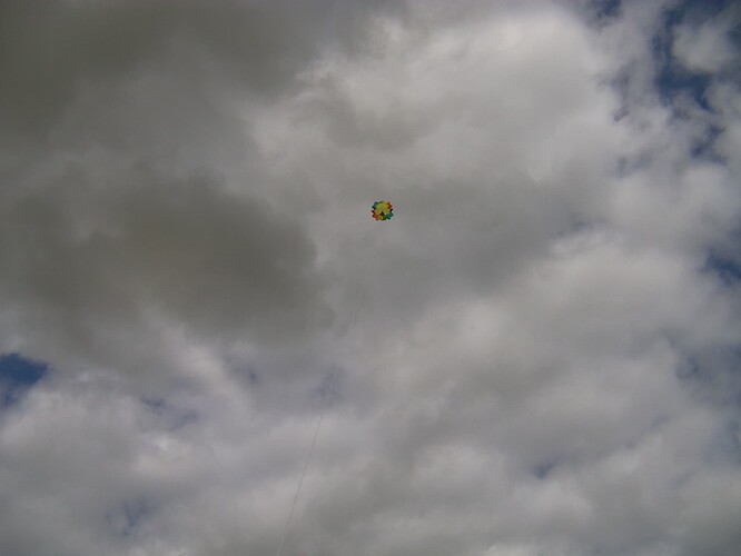
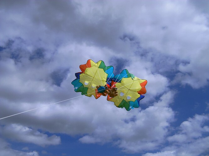
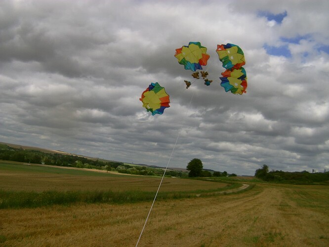
Today I tested parachute kite clusters of two then four unities, then a parachute kite alone.

Parachute kite cluster

Parachute clusters are tested and provide good results.
Things are different with parachute kite clusters where you must manage both drag and lift during the complete flight. As a result a single parachute kite flying well would lead, when multiplied, to a cluster flying not well. That said this challenge is open.

In this video a single parachute kite was tested, then clusters of two then four parachute kites.

Unlike the previous similar test the present test was performed with complete parachute kites as they are sold, with their respective bears increasing ballast and stability. They are a bit like parasails which also have to work with a minimum load for stability.

Some photos:

Aren’t all parasail systems governed by the Cosine-cubed law? At a tether angle of 30°, the power losses are 35% due to this law. I believe that this value should be reflected in the formula for tether tension where the area is not the true area of the parasail, but the subtended area due to the angle of the parasail to the horizontal. This loss is considerably more than the possible losses due to wake separation.

To avoid these losses, would it not be advantageous to launch the parasail system from a high tower so that the tether is approximately horizontal? This tower could be a light weight system, supported by guy wires. At the top of the tower there would be a transfer pulley, which will direct the tether tension to a ground-based generator.

Advantages:

  • All parasails are at a higher elevation, and so the average wind velocity is greater.
  • Parasails will not fall to the ground if the wind stops blowing.
  • Land area around the base of the tower can be used for other purposes.
  • When not in use, the parasails can be stored vertically.
  • Launching and landing the system is easier.

Disadvantages:

  • Additional costs.
  • Small efficiency loss due to the transfer pulley.
  • For changes in wind direction, the transfer pulley must be re-oriented. (The present system has even more problems if the wind direction changes.)
1 Like

The tower system is mentioned at least on Crosswind Kite Power with Tower which is a concept studied by @floba , and for the cosine loss reasons you mention.

However, in this chapter it is shown that tethering the kite to the top of a tower instead of to the ground can have advantages: Most notably, the “cosine loss” is reduced, i.e. the misalignment of the wind velocity vector and the direction of the traction power transfer.

My opinion: a train of parasails aiming to reach several hundred meters of altitude or even more than a thousand meters as mentioned in the poster that you and I cited, will only be raised to the height of the tower. Said tower will undergo cantilever efforts. That’s a lot of inconvenience for minimal benefit.

True, but a parachute flying horizontally is not more a parasail (so a sort of parachute kite) which has also lift in addition to drag in order to rise. And rising is needed in order to reach more consistent and powerful high altitude winds.

A lot of advantages were mentioned. The list is likely not exhaustive.

To expand on the last advantage mentioned, one reason launching would be easier would be the higher wind velocity at the top of the tower, which would also give you a higher capacity factor.

Some mast-based launch systems are used as seen on the videos below. Such masts could also be used for parasail launch and landing. But, in my opinion, “tethering the kite to the top of a tower instead of to the ground” for another purpose (decreasing cosine loss) would add an unwanted cantilever effect that is proportional to the length-height of the mast, without adding a significant advantage for parasails flying at hundreds of meters high, even more than 1000 meters.

Video 4: Setup and use of the mast-based launch system for the 25 m2 LEI V3 tube kite

The stated main point of AWE for the last 16 years has been getting rid of those dreaded towers.

This is reminiscent of the vertical-axis people, who typically start by reminding the listener that the advantage is not needing to aim into the wind, but then their first “rescue” attempt is to make it responsive to the wind direction after all, by adjusting the blade pitch in response to the wind direction.

The ongoing theme is to start with a bad idea, state its “advantages”, then promptly remove whatever those “advantages” were in the first place.

And so it goes - just like the La Brea Tar Pits… nobody escapes… :slight_smile:

1 Like

Because skysails have such a good depower they can use a tower without excessive cantilever
(Their nose line launch and recovery helps massively too)

KitePower no longer use a tower

At Windswept, the presumption for our tower launch tests (Barely tried) was that the upwind tension to the mast head from the turbine would be enough to counter any cantilever effect on the mast… relies on the mast being in the correct downwind alignment, or a tilting mast…

Single skin kites could might not hold as much rain.

Current parasails usually are open then closed numerous times, making them suitable for a yo-yo use, and resist the harsh marine environment, including water and rain. Indeed parasails are somewhat like single skin kites, and their round shape is probably well suited to letting water escape.

The fabric of our parasails is crafted from 6.6 ripstop nylon yarns, silicon-coated on both sides to prevent air penetration. This silicon coating also protects the parasail fabric from corrosive chemical reactions that can occur when in contact with salty sea water. To ensure longevity and vibrancy, our fabrics are stained with UV doped pigment to resist fading under the sun.

We offer two different fabric qualities to cater to different budgets. Our standard series fabric has a thickness of 1.6 oz and boasts an average service life of 2500 flights or more. For those seeking a lighter option, our professional series fabric weighs in at 1.3 oz and can endure approximately 5000 flights or more, depending on usage.

1 Like

This seems to be confirmed for some recovery parachutes on Experimental Characterization of Drag Coefficient of an UAV Recovery Parachute, Vu Dinh Quy, Le Thi Tuyet Nhung*, Tran Minh Duy Dat
Hanoi University of Science and Technology, Hanoi, Vietnam, figures 6 and 8
.

After dropping the Cd seems to be stable (even when the wind speed is still increasing) as shown in figures 6 and 8.

An interesting Dave Santos’ observation:

Why Cd decreased anomalously in Pierre’s Parasailing example

“the drag coefficient seemed to decrease as wind speed increased.”

Explanation: As wind velocity increased, AoA of the canopy decreased (inflection point at payload), as it further overcame its own mass (reduced kite stall-angle). Increased Cl then offset decrease in Cd, maintaining overall flight equilibrium. Further increase in velocity would result in Cd gain. Cd is a strongly non-linear function, only approximately linear in narrow ranges.
Nice example of higher-order reversals of lower-order aerodynamic assumptions!

However the publication (from the last link of my previous comment) is about Recovery Parachute where there is only drag function, so only Cd, and no Cl.

The link (in the quote of the previous comment) is about parasails: so Cl and Cd are concerned. But a truck was performed in order to measure different (relative) wind speeds. So we can guess that thrust (lift and drag) was measured:

The weights used for the test were 90, 125, and 230 lbs. In order to record the data accurately, two team members operated in unison, recording the wind speed and tension reading at the same moment the parasail appeared to be flying in a level fashion with the rope at approximately 40 degrees above horizontal.

As the elevation angle was fixed, there was no variation in Cl relative to Cd.

My observations therefore do not corroborate the explanation cited at the top of this commentary.

From Dave Santos:

Pierre continues the Forum discussion, with some questions still in play, given the complex mix of factors.

With primary tether angle levelized and tow velocity free to vary, the primary figure-of-merit is the ratio of payload mass to canopy mass. The lowest Pm/Cm ratio with the lightest payload presents the highest Cd, as expected under kite stall-angle response at minimal flight velocity at angle given.

The trend is confirmed, although with much closer Cd values: A Numerical and Experimental Study of the Aerodynamics and Stability of a Horizontal Parachute

Excerpts:

2. Experimental Setup The experiments were conducted under the free-flow conditions (i.e., at the atmospheric pressure and temperature). The test rig was mounted on a vehicle, which moved with the speed of 8.3 to 33.3 m/s.

The figure 6 seems to show that the Reynolds number corresponds to the air speed, since the tested parachute is the same. The Cd varies at low Reynolds number (Cd from 1.75 to 1.64) then slowly after (Cd of 1.6 at 33.3 m/s): so the variation of Cd is generally minimal compared to other measures.

About stability, page 6:

It may be noted that by increasing the vent ratio, the critical Reynolds number at which the parachute started to oscillate is increased. For parachutes with vent ratios of 8% and 12%, these critical Reynolds numbers are 171100 and 292600, respectively.

1 Like

See also High drag coefficient - #43 by PierreB. I reproduce the link of the publication: A Numerical and Experimental Study ofthe Aerodynamics and Stability of a Horizontal Parachute, where the figure 3 shows a similarly shaped curve but with more different values of Cd, and where “the drag coefficients are calculated numerically” (Abstract).

I mention also two very interesting observations from Dave Santos:

Pierre continues exploring interesting aerodynamic complexities of kite-like objects, citing the paper linked below, which in turn cites prior work along similar lines.

Here the higher relative velocity (higher Re estimation) lower Cd anomaly has yet another obscure cause, this time mostly inherent to drogue canopies with shroud lines. Many of these sorts of experiments and their simulations only explore narrow bands in tunable parameters. Narrow dynamical observations may show local linearity in overall nonlinearity, or complex reversals of general dynamics.

As velocity increases from zero, a drogue inflates, Cd at first rises roughly according to increased projected area. However, as velocity continues to rise, new dynamics present. Projected frontal area can decrease by “jellyfish” variation. Enhanced laminar bypass flow by the billowing gores can reduce Cd somewhat as a golf ball with dimples flies farther. Elasticity in shrouds and their rigging trigonometry figure strongly in observed dynamics. Re is a slippery parameter, for example, effective reduction in frontal area factors Re lower. And so on.

This student ME work did not dig too deep in an AE subject (aerodynamics), a lesson in caution for kite pros.

In general, Bluff-Body Cd is a function of frontal area, but one must control carefully for higher-order complexity, to not be puzzled or misled.

The second Dave’s observation (below) concerns the possibility of exploiting and even causing instability as a means of power take off (PTO). I had experimented a little with a parachute oscillating due to instability, and capable of exerting a (limited) action on winch-generators (here dog leashes) alternating.

A whole further subject is drogue oscillation dynamics (treated in the paper by Strouhal Number) which can be passively tapped as free-energy for AWE, which kPower over a decade at subscale mastered in praxis, but active control AWES developers disregard. All aircraft are complex oscillators. Kite Oscillations are normally damped by design but can just as well be amplified by design, within stable limit cycles.