Any ideas on how to change the length of an endless rope drive during flight?

I mentioned that as an alternative to Tallak’s idea. Your idea would help I hope in keeping the tension more constant and in being able to choose different heights.

I would still like to find a way to automatically change the tether length from very short to fully extended. If I have that, automatic launch and landing might become possible. On that, I’m thinking increasing the wrappings around the pulley on the ground might work. If that doesn’t work, I was considering something like locking the ground station pulley and winding the loop on a secondary drum, but then production stops the moment the ground station pulley is locked.

For me, these questions are still far into the future.

1 Like

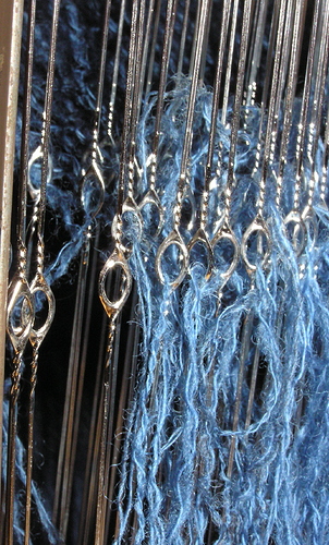
KiteLab Ilwaco successfully tested Heddle Pulleys as the traditional mechanical basis to alter length of working lines, including loops. Heddling can be done on the ground with spread anchors and vehicles, or in the air with kites and drogues. This is great for control inputs, not just altitude adjustment or retraction.

2 Likes

Thanks. I assume you mean something like this:

I was looking for similar. Is this the term used in kiting or engineering and do you know where to buy low friction ones for use in kiting or similar? The Wikipedia page doesn’t list uses outside of a loom.

That is an application of a plain bearing. I wonder what the ideal diameter of a plain bearing would be to limit wear when the rope makes a 180 degree turn? I think a plain bearing might be better as they are better suited for high speed operation. A pulley would rotate at several thousand rpm.

Heddle is the term of art in AWE for the same rigging principle in Looms and Sailing (see “lazy-jack”). As for the friction of a simple eye v. a pulley, it varies from case to case, and is low enough many purposes, like simple Fairleads.

1 Like

How about 2 parallel rows of pulleys which are moved closer or further apart. The drive cable (low tension side) passes around the pulleys and will shorten or lengthen based on the distance between the parallel rows.

1 Like

You mean like a single shoelace lacing a shoe with you pushing the eyelets further apart to get your foot into the shoe?

I think you’d have to consider how much friction a pulley would generate. If each pulley results in a 3 percent loss of efficiency, 10 pulleys would give you a loss of 100(1-0.97^{10}) \approx~ 26 \% I think.

I like the idea but maybe there are other ways of doing it that give you more travel with less pulleys. Maybe different (3d) geometrical shapes. Or more pulleys on a single axis if that might reduce friction.

Move the generator along ground, with a fixed pulley at a second coordinate at ground level?

1 Like

That sounds like a very easy thing to do, if you have the space to do it. And I can’t think of another way you could vary the length of the (airborne part of the) loop as much. Only thing is you’d have to think about what to do about the tether dragging over the ground once there is some distance between the pulley and the generator.

You could add extra idler pulleys to keep the tether from the ground, you could build an unreasonably high tower for the pulley, or you could, instead of putting the pulley at ground level, attach it to the end of a tether – that you can wind in and out – so you can have the pulley suspended at a height of your choice, for example. If you go with the last idea you could also use the pull on the pulley tether, or the lack thereof, as a signal to do something, if you for some reason didn’t put an anemometer somewhere else.

Edit: This doesn’t seem like a solution you could use for launch and landing as then your generator would be far from the pulley, and the pulley would be close to the ground, causing the tether to drag over the ground.

That’s how ampyx is doing it:

1 Like

How about building a giant shoe with pulleys and let an old lady live in it and power it with the AWE device so she doesn’t burn it down using candles?

The below comment was mostly in response to this comment: Flettner balloon and VAWT side by side - #14 by PierreB but I think it is better here.


I am not aware of any mechanism that allows a single continuous loop to be reeled in and out while the loop is being driven. I am inclined to think that is mathematically/geometrically impossible, it would break the loop. To achieve that, I think you probably need a connection point somewhere in the loop, that is then caught by a mechanism, decoupled, and then two drums each take one end of the tether and reel them in at different speeds.

Assuming for example the airborne and generator pulley are both rotating clockwise and are driven by or drive the tether at the same speed and you want to maintain that, also assuming that the two additional drums are located below the loop, one closer to the airborne pulley and one closer to the generator pulley, you’d decouple the two ends of the loop and fix them on one drum each, then keep the drum closest to the airborne pulley static while the one closest to the generator matches the rope drive speed and wraps the tether around itself. That would be powered descent then.

While the kite is on the ground, you could rotate the airborne and generator pulley counterclockwise to wrap the tether around the drum closest to the airborne pulley and unwrap it from the drum closest to the generator pulley, to make it so that during ascent the airborne pulley can rotate clockwise. Powered ascent is still not possible I think like this. For that I think the generator pulley needs to spin, and for that the drum closest to the generator pulley needs to spin, which would be counterproductive as that would wrap the tether around that drum again – or you could make a loop at the end of that tether and connect it to the tether that is exiting from the other drum and let the speed that this loop slides along the other end of the tether control the reel out speed, but I don’t know how that would work

If you fill the balloon with a lighter than air gas to help with the launch it will be blown down in high winds, so you could only launch in low winds. How much this is a problem depends on the buoyancy of the balloon and the strength of the wind.

You could instead use a different lifting mechanism that does depend on wind. Best would probably be to spin the balloon already while it is on the cradle, but that would then also start unreeling the loop, if the loop was wrapped around the airborne pulley. Better then to add an additional airborne pulley that the loop goes around that can then be decoupled from the airborne pulley while not producing power, on the cradle and during ascent and descent.

With the additional airborne pulley you don’t need the rope drive to be moving during ascent and descent, so you can keep the loop intact. You can decouple the extra pulley from the airborne pulley and reel the loop in or out. You still can’t do powered ascent and descent, or powered from the ground generator at least.


As sketched, I expect the structure to collapse in the same way that the Magenn structure collapsed.

I don’t like the concept, or balloons instead of kites in general. I do like rope drives and I think they make a good match with rotating balloons. So I think my concept for a rope drive here is interesting at least for @WindFisher. IIRC they use four drums, they could instead use 2 ground based pulleys and eliminate the need for discontinuous production. There’s still the problem of no powered ascent though, but they use helium for that. …Or wait, can you extract much more energy from the pull of the balloon than from its rotation?
Or I used to. But rope drives seem to be need to be replaced often and don’t seem to be able to do powered ascent. So I think it’s probably better to integrate the above extra airborne pulley into a carriage that also includes a motor/generator and make it flygen instead.

Another idea then might be to put multiple balloons in a train. You’d do something like put an extra non- rotating ring around the primary airborne pulley, or disks on either side of balloon, not touching it except through bearings, that the tether/cable going to the next balloons would slide through. The carriage would be permanently fixed to this and the tether/cable would also slide through it. The carriage/ring would clamp to the cable at a spot where an electrical connection was made possible. Since the balloons would be flying at different radii and with that speeds, you would rotate them at different speeds to change their L/D ratios.

This start looking a bit like the Brainwhere concept, except this uses crosswind flight, balloons instead of VAWTS, and I don’t remember how it handled, or if it described, the reeling out process.

Thinking about BrainWhere, the extra ring around the balloon probably isn’t needed. You can make it so that the carriage rides along the airborne pulley and the carriage wheels go around it, fixing it to the pulley. …If it were not flying crosswind, maybe… If it is flying crosswind that puts a lot of stress on the carriage/pulley, sitting on the side and some distance away from the lift force creating a large moment arm. You instead want the tether to be in line with the lift force, entering the ring at the center of the balloon below and exiting at the center of the balloon above, so you would need the ring after all, or part of the ring.

Like I say, I am not aware of any mechanism that allows this.

Yes, that might be the beginning of a mediocre idea, not that my similar one was that much better. I wonder how much extra tether you would need for this. Say you want the loop to have a length of 200 meters but to get to that length, the airborne pulley needs to rotate for a minute at 20 m/s, which would unwind 1200 meters of tether from one drum. The other drum would also not stay static during that time, reeling in instead, slower than the other drum is unwound, also adding some, but less, tether length to the rope drive, so you might consume 10 times as much tether as you need. Then at the end, still one end the tether is still partly wrapped around a drum. So I don’t know how that would work.

Another idea would be to now add an extra drum next to the loop, rotating at the same speed as the tether, with now an extra arm adding wraps around this drum, like how you would reel in a kite by using one hand to wrap the line around a drum in your other hand. This would work I think, for short lengths. This extra drum could also replace the ground station pulley.

I remember seeing a YouTube video around that time, probably linked on the Yahoo forum and since disappeared, where I think I remember the balloon deforming from the torque the balloon placed on the generators, or maybe from their weight. My memory is fuzzy on it collapsing further. The two videos I could find now don’t have the generator attached and have just the balloon spinning freely. Someone like @dougselsam might have commented they should have connected the two generators together with a pole.

A random video showing a spinning reel on a fishing rod

Adapting this to the proposed system is left as an exercise for the reader for now. The goal would be reducing the number of bends the tether has to go through and deciding if you want to align the drum along the minor or the major axis of the rope drive to achieve this. The rotor wrapping and unwrapping one end of the tether on the drum would need to not interfere with the other end of the tether leaving the drum.


I don’t know how this would work, but an idea inspired by this idea inspired by my idea:

Now you have the two drums like sketched, the tether comes from the airborne pulley, it wraps around one drum a number of times, goes through a tether tensioning device connected to this drum, then some distance to a tether tensioning device attached to the other drum, wraps around that drum a number of times, and again goes to the airborne pulley.

Lengthening and shortening the rope drive is now done by varying the relative speeds of the drums. If it is shortened, the tether winds up laying on the ground or in a bucket between the two tether tensioning devices.

This is the start of an idea. I don’t know if letting the tether lay on the ground or sit in a bucket is a good idea or what other ideas there might be.

I just realized (again?) that this topic has existed for years.

It’s partly that, or rather that some of your observations (see quotes below) encouraged me to see, in two times, what it was possible to do for takeoff and landing (if we want to use the rotation and the Magnus effect) by using the generator as a motor, knowing that it is not possible (to my and your knowledge) to vary the rope drive (loop or belt) length while it rotates the Magnus cylinder.

Me neither:

It remains to be seen: in the meantime, thank you for the compliment.

To get back to the basics, the rope drive (loop) does not allow you to take off using the Magnus effect.

But the @WindFisher double winch for one rope allows this maneuver as well as other maneuvers. This is an interesting innovation to credit this company. On the other hand, this system works specifically in yo-yo pumping mode which alternates the direction of rotation and the unwinding and/or winding of each of the winches in transfer of rope.
It would not work for long in continuous power mode with rope drive (loop, belt).

In the sketch I made and you quoted, after takeoff the rope is transferred from the double winch to the ground pulley of the rope drive system (loop, belt, rope without end…). I don’t know if this can work, but it looks possible.

This described device (with “two drums”) looks to be on the basis of the double-winch-one-rope from @WindFisher.

An another possibility, for vertically stacked balloons or other things (Kiwees?) is using the WindFisher double winch in the lower part in order to vary the rope length for takeoff and landing operations, then a chain of loops (rope drive systems) to connect the balloons two by two as also here.

Both your and my idea, and your later idea that I copied the sketch from to here, cannot work I think unless you solve the following problem. As they are all mediocre ideas with the breaks in the line, with better alternatives available, and the problem being perhaps unsolvable, I wouldn’t bother. The problem: Say you want the loop to have a length of 200 meters but to get to that length…

This now is outdated. This topic has several older concepts, and now two new concepts, the fishing rod spinning reel one, and my latest two drums one with the extra line being dumped, in one way or the other, between the two drums.

These concepts do all allow the rope drive to power the kite from the ground during reel in and reel out. I am only interested in concepts that can be mounted somewhat compactly around a central spinning axis to allow for crosswind, rotary, flight. The spinning reel concept seems most promising to me.


If this is solved and the losses and line wear turn out to not be problems, which they likely are however, you could use this to do bounding/yoyo/reeling rotary MAWES, potentially supported by lifter kites. The fuselage would be clamped to one side of the rope drive.

Similarly, but now with extra lines that go to the wings or fuselage, you could do rotary MAWES flygen, but now with the airborne generators replaced with the rope drive. Different kites would fly at different speeds, so they would have differently sized pulleys. This likely also has problems, now in addition to the other problems you’d have a lower rope drive tension for example and the rotors are likely not going at their optimal speeds.

After just three days?

Is also the “concept” of “two drums” outdated? As I just wrote, it looks like the WindFisher double winch. But it’s difficult to judge: WindFisher’s description is very clear and includes a drawing, unlike yours.

“What is well conceived is clearly stated,” wrote Nicolas Boileau in 1674.

Yes, my the first one and your two. I repeated the problem that the concepts with breaks in the line have several times, one of the problems at least.

I described my two new concepts here sufficiently clearly. You can look at a spinning reel and imagine how you would change it to make it work in this situation, and you know that if you wrap a line around one shaft and then around another, the length of the line between the shafts changes depending on the difference of the rate of rotation between the shafts.