Chanterelle bridled soft shaft (non working)

I have been investigating an idea I have had about a soft shaft for rotary rigs. I have called it the “Chanterelle” shaft, though the name is probably soon forgotten as I have not found any merit in the design.

The idea is to make a completely soft shaft with no expanding rings. But instead, add some bridles along the tethers so that the overall curvature is convex. The convex curvature then allows some more rotation of that segment before the shaft collapses. To put it in other words; the convex shape of the tether provides expanding forces instead of using stiff/compressive elements.

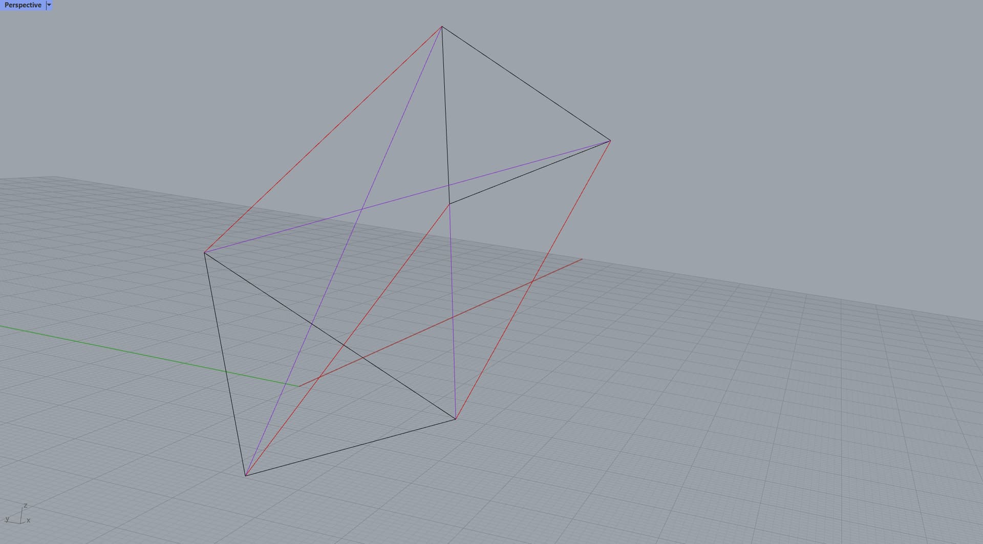
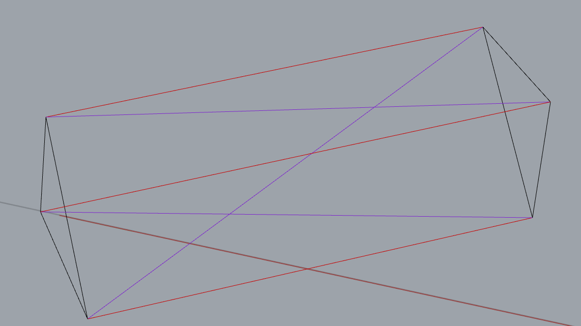
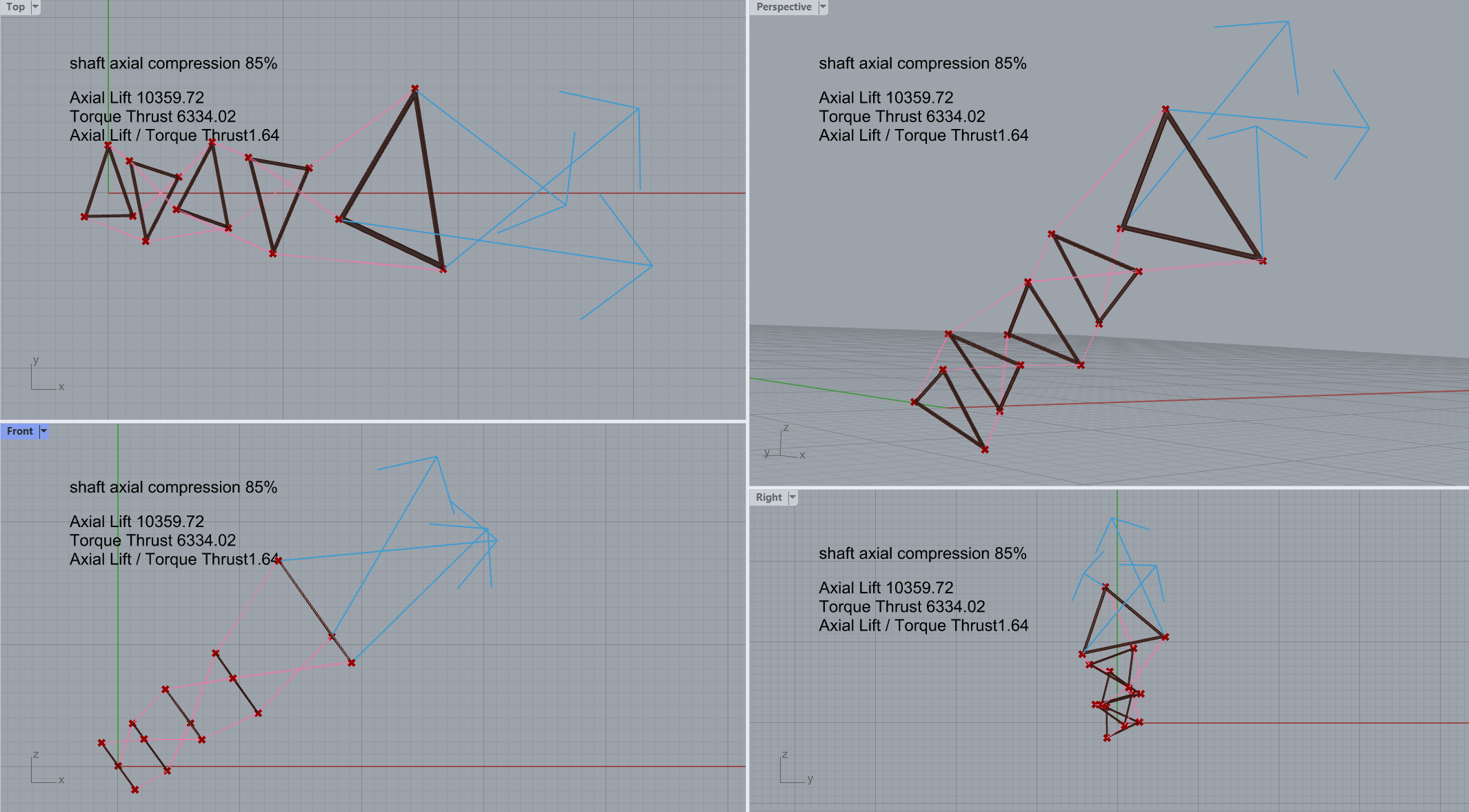
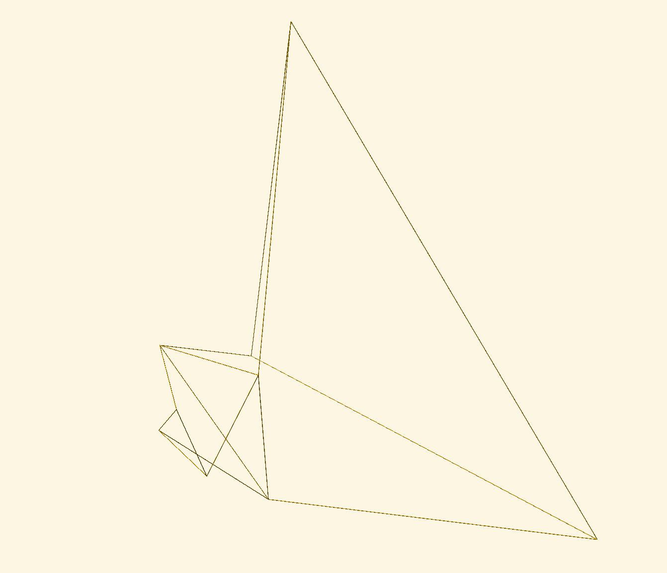
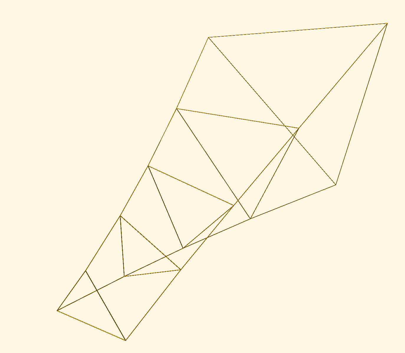
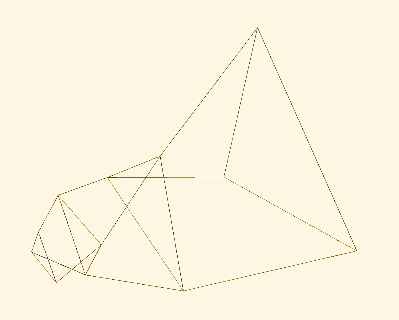
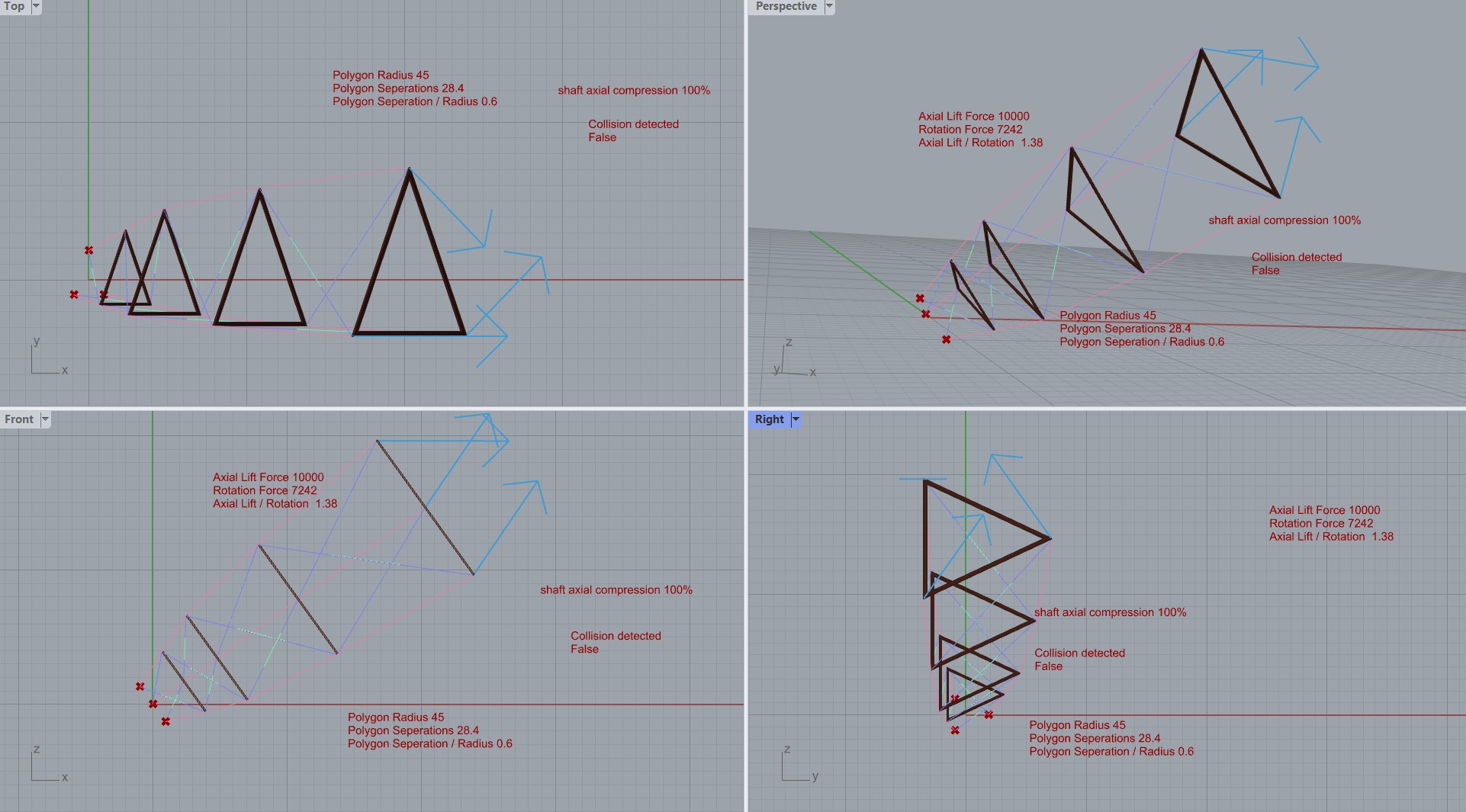
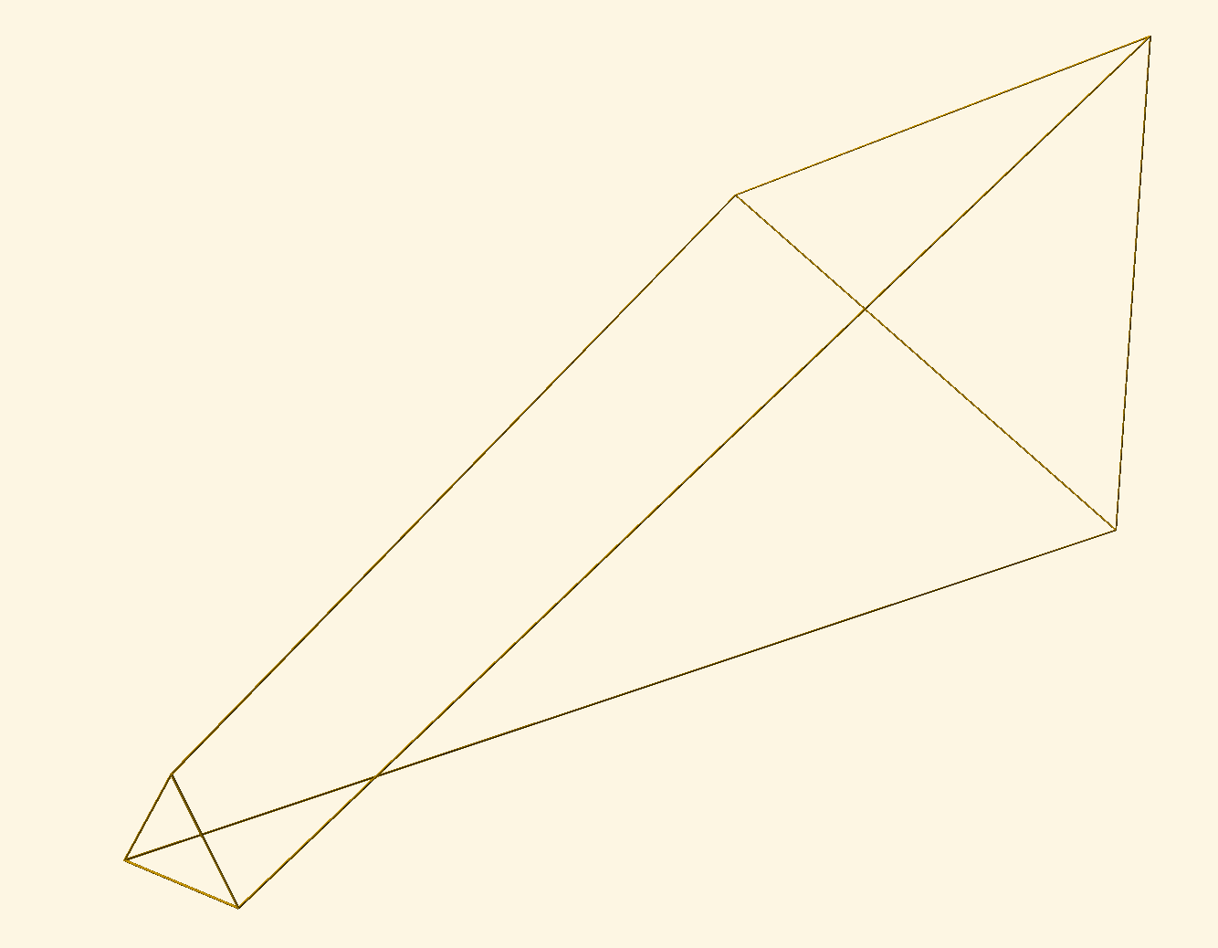
I have added pictures of a shaft with no bridles (not Chanterelle), and a Chanterelle shaft with 6 segments. The distribution of radii ensures the outline is convex.

I will not go through all my calculations here, but it is nice to assume that the tension in the shaft is constant. This means that the tether tension varies depending on the amount of twist. The tether tension could be different at different places in the shaft at any one time.

So having

  • T_\perp: the tension in the shaft
  • R_n: the radius of the shaft at any node (bridle, ground shaft or kite plane)
  • l_n: The length of the tethers between the nodes
  • \delta_n: The amount of twist between two nodes

We should arrive at a moment

\tau_n = \frac{T_\perp R_n R_{n+1} \sin{\delta_n}}{\sqrt{2 R_n R_{n+1} \cos{\delta_n} - R_n^2 - R_{n + 1}^2 + l_n^2}}

Because the moment through the shaft must be constant \tau_a = \tau_b for any a and b, this equation may be used to calculate all \delta_n iteratively from node to node.

The complicating matter is that when you twist far enough, the bridle will change from tensile to compressive. In practice you must detect if this is happening and then not use that bridle in the further calculations. One can see that when all bridles are slack, we are essentially left with the non-Chanterelle shaft. So given enough rotation, eventually we will not see any benefits of the Chanterelle design.

I used a test to see if the curvature of the tether at a node is inwards or ourwards. If it is straight between three nodes, that implies that the bridle is slack. Thus if the curvature is inwards, we must disregard the bridle.

I will not go into details about how I calculated this because I don’t think it is of much interest to you. But ask for it if you want to see it (its a bit of work for me to write down and explain all the equations involved).

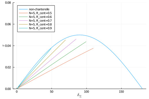
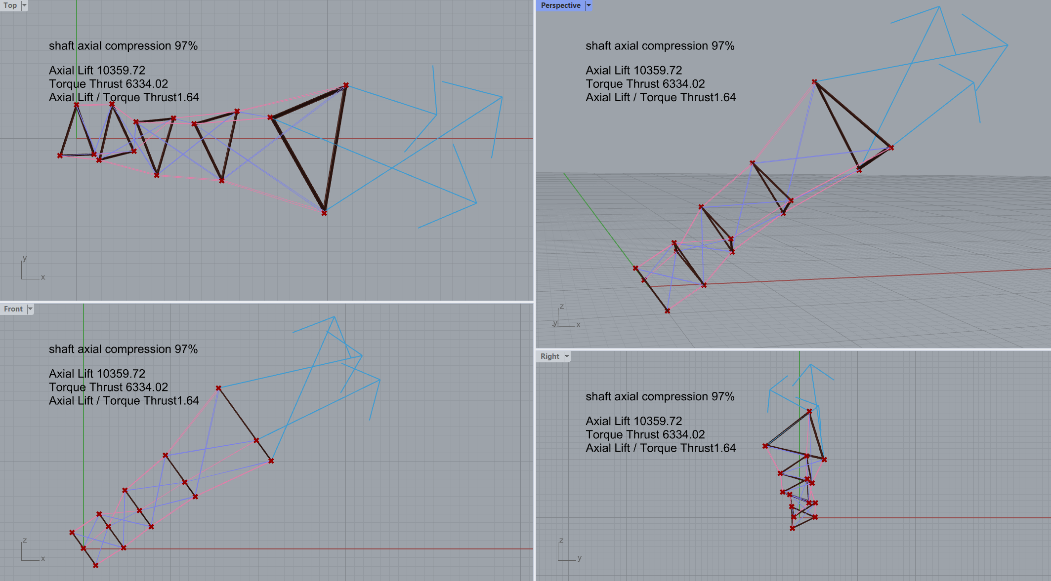
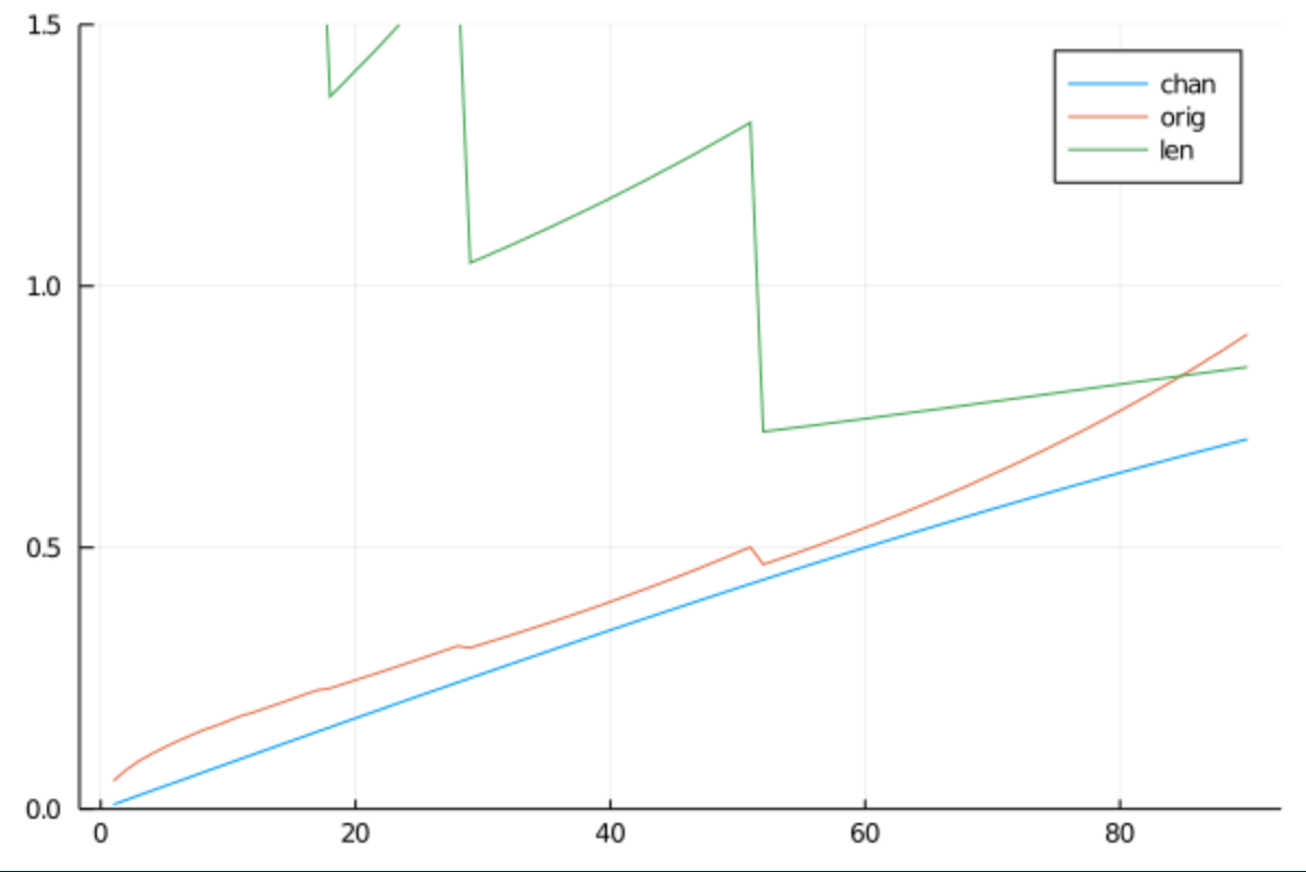
Anyways, when plotting the maximum torque vs the total twist in the shaft, the plots would look something like this:

This is for a Chanterelle shaft with varying middle radius, length 20 m, radius at either end 1.0m, looking something like this:

You can see that the tethers are pretty straight at this point of maximum tension

So, my experiment ends here for this idea. I have tried a few more things to see if I could find a configuration that could increase the moment the shaft was capable off, but never found anything.

I think future useful work could involve a kind of Chanterelle shaft with compressive bridles, giving enough moment capability in the shaft, but minimizing the size and weight of the “rings”.

5 Likes

Great to see analysis of tensile rotary transfer being considered in such detail.
Well done @tallakt

2 Likes

Do you suspect that this demonstrates evidence that the simplest method of linking TRPT polygons will be the most effective …
Or would a system with additional bridling still likely improve performance by some metric? (like torsional rigidity / rotational stiffness)

Certainly if we added another bridle (purple) between 2 consecutive triangles (black lines below)… e.g. where there are already straight lines (red lines) between the triangles, adding extra trailing lines (purple lines) to take the torque


The purple lines will make the TRPT system between the 2 triangles more rigid in torsion instantly with very little tension between the triangles.

This extra bridle TRPT will initially be much less dynamic and the system will stay rigid with tension shared between the 2 bridle lines through changes in L/D, gusts and such up to the limit point which is when the torque/tension ratio exceeds that which the purple lines can support

Looking at the shaft from side on we notice though that the purple lines make for a much slimmer shaft than the red lines


Just like if the system was only red lines
Notice the red lines will not be supporting any torque beyond that which the purple lines can.
The red lines only support inline tension.

Must double test this with a model … I think the system collapses quite quickly (certainly for a triangle TRPT polygon) beyond the torque/tension ratio point being exceeded

This form of TRPT undoubtedly offers some advantages and live monitoring of the line tensions would provide a robust solution to TRPT stability.
I suspect there is more drag with the extra lines.

2 Likes

I don’t expect tester drag to be a major issue because the tethers can’t be very long to begin with, because of the limitation in moment transfer. For me, more tethers are ok except for handling.

The bridle you have shown kind of combines a twisted shaft of \delta = 0 and \delta = 90^\circ for the red and purple tethers respectively.

The shaft will be stiffer for it.

I am not sure if the stiffer shaft is a benefit though. It will collapse more nonlinearly and monitoring the phase difference is bound to be more difficult. It really depends on stability in gusts.

This shaft has very little mass, so it may be possible to have very little oscillations if the kites are tightly controlled.

1 Like

Congratulations @tallakt for this preliminary study on which a great scientific publication could be built, with the possible collaboration from @rschmehl, @someAWE_cb , @Rodread , @Ollie, if each of you want, for a main topic. Indeed a soft and light shaft would be useful for TRPT.

I have some minor questions, concerning the graph, unfortunately not being a mathematician:

image

abscissa: x-axis (the amount of twist in degrees?)
ordinate: y-axis (0.02; 0,04…?)
N = 5?
R_cent?
Thanks.

1 Like

I settled a couple of similar models using the different bridling patterns.
And you are correct @tallakt the response of the shaft with extra bridling is initially and overall stiffer but more non linear… Here are the final converged results of the first two I have compared.

With just straight lines there is much higher shaft compression as the straight lines have to compensate for all of the torque.


When the extra bridle to the trailing polygon is added this takes up the torque however … look at the section between rings 2 and 3 The trailing bridles torsional rigidity has collapsed and they are very close to touching. The previous straight lines now take most of the torque through this section. There was a noticeable collapse moment in settling this form.

Might try the comparison again with Lower Lift/Torque

1 Like

The y-axis is the amount of moment transferred for 1 N shaft tension. I have not gone to the effort of seeing whether this amount of torque is even useful. Certainly for the very long slender shafts, I dont think its usable.

A value of 0.05: If the total kite lift/shaft tension is 1000 N, the moment is 50 Nm. The energy if rotating at 2 rad/s would be 100 W. Using the formula for power of a rotating shaft: P = \omega \tau

N = 5 means there are 5 segments.

R_{cent} is the shaft radius at the center of the shaft. The radius at either end is 1.0 for this plot if I remember correctly.

I included the plot for illustration purposes. Sorry for being sloppy with the explanation.

I could write a more formal paper which would take a few days, time I dont have unfortunately.

I did the effort to check that the shaft scales though, so for a well designed shape, any size rig may be built with such a shaft

2 Likes

So maybe I found a configuration where the Chanterelle design will double the moment through the shaft. It may serve as a proof that the design works. Even so, I dont expect it will work in very useful configurations.

The example is pictured below:

As you can see, this particular configuration allows a shaft twist of a full 180 degree without collapsing. In this way, you get almost double the moment transferred compared to a non-bridled version.

This design only seems to work with very short shafts, where the ground radius is small relative to the kite looping radius.

The radii are: 1.0 m, 2.5 m and 7.5 m
The segment tether lengths are: 3.0 m and 7.5 m

The moment transfer factor is 1.9 for the Chanterelle shaft, and 1.0 for the non-bridles shaft. To get the maximum possible moment transmitted through the shaft, multiply this factor by the shaft overall tension (eg. approximated by the lift of your kites).

The cone angle of the shaft is almost 100 degrees necessitating a tower or a 50 degree elevation angle. And the shaft length when compressed is only 5.6 m.

If I have not miscalculated, at least it proves the idea has some merit, though maybe not to be of practical use (I have not yet studied this).
chanterelle.scad (2.3 KB)

1 Like

To be fair the “black and purple” soft shaft may have a big benefit to my original proposal.

The shaft will be of constant length until the point where it buckles whereas my original proposals all shorten under load.

I believe the shortening leads to an undesired positive feedback loop so that in a gust, the kites will pull harder causing increased moment and a compression of the shaft. When this happens, the kites are pulled upwind due to said compression, which in turn leads to even higher moment on the shaft or a speed increase… So this may well oscillate in gusts. Only way out of this is to have a really good (advanced/complex) control system at the kite and ground.

The soft bridle with diagonal bridles evades much of this by not compressing from moment changes.

1 Like

Is everything in the Chantrelle designs soft?
I had thought there was rigidity in the polygon sections

I think yes.

I have a similar question to @Rodread : are the triangles rigid? I think yes but I am not quite sure. And the black triangles there “(certainly for a triangle TRPT polygon)”?

Everything is soft. Though rigid bridles may be considered if you like. I have not. Maybe it is a viable option to get optimal weight… The analysis though will be slightly different. But seeing the failure of a completely soft shaft, the rigid bridle may still be a good idea

Intuitively I wouldn’t choose that shape as I would guess that the torque you can transfer is limited by your minimum R . What do the forces look like if you made it like a tensile downwind rotor with the bottom, lowest radius, node rigid (which it perhaps has to be to connect to a generator) and that marking the bottom of a truncated cone/funnel? At the top of the funnel would be your kites.

This reminds me a bit of space nets (Conrad Roland) Video testing forces: HowNOTtoHIGHLINE

1 Like

Well these things are very complex and sometimes counter intuitive. The equations I am getting from Maple are too long for print in a report.

The shape you describe works but still the moment transfer capability is less than the non bridled version, except for extreme non-practical cases.

I consider the ends of the shaft rigid. The ground side will actually be rigid, and the kite side will be expanded by the kite lift and centrifugal force.

Now, if you shorten the shaft, if you look at the moment of a shaft section formula, you see that the moment increases. This means that if you split a soft shaft in two halves, the middle radius at the split may be less than either end, but still maintain or increase the moment capacity of the shaft.

The «joker» is taking into account at what twist of the shaft the soft bridle will buckle. So you will not be able to twist the split shaft 2X180 degrees before this happens.

The more convexity, the more expanding force is applied to the shaft, extending the amount of twist before buckling. But more convexity also means smaller radius at the middle. So its kind if a catch-22.

My conclusion overall being that one can’t really increase moment capacity of a soft shaft using this technique.

2 Likes

Let me provide an example. I made a script to build a Chanterelle shaft with an initial shaft segment (length and radius of the two bridles, and twist of initial shaft segment). The script will build a complete shaft up to a minimum kite radius by adding segments in such a way that all segments buckle at the same time/shaft moment.

The following plot shows how these auto generated shaft designs fare relative to a non-bridled shaft

On the x-axis we have the twist of the original shaft segment in degrees, on the y-axis the moment factor. Multiply the moment factor by the shaft tension to get the maximum transmitted moment before the shaft buckles.

The red curve represents the non-bridled shaft with the same total tether length and the radii of the first and last matching those of the generated Chanterelle shaft.

The blue curve represents the maximum torque factor of the Chanterelle shaft.

The green curve represents the total tether length of the shaft (note the shaft length is a bit shorter due to curvature on the shaft)

The input to the shaft generator is: radius 1: 1.0 m, radius 2: 1.0 m, minimum kite radius: 3.0 m. Also a bridle is added every 2.0x the radius from which it builds on.

The shaft looks like this this for \delta_1 = 30.0^\circ. \delta_1 is the twist of the first section closest to ground, at which the shaft buckles.


Touching into the topic of rigid bridles, if we allow the compressive force at each node to be equal to 5% of the shaft tension towards the centerline of the shaft, we may increase the length of the shaft from 10 m to 14 m. The plots look something like this:

From the graph we see there is still little improvement in performance relative to just removing all bridles altogether. Still, the Chanterelle with rigid bridles may perform slightly better in some configurations.


Finally, if the bridles can really handle a huge compression (0.5x tether tension), a Chanterelle-rigid shaft like this one offers twice the moment transfer relative to a non-bridled shaft

shaft_build_sections_until_radius(deg2rad(59), 2.0, 1.0, 1.65, 3.0, length_factor = 2.0, compressive_force_factor = 0.5)
  :radii                  => [1.0, 1.65, 2.97956, 4.7466]
  :sum_lengths            => 11.2591
  :deltas                 => [1.02974, 0.741188, 0.57851]
  :lengths                => [2.0, 3.3, 5.95912]
  :cone_degrees           => 22.0816
  :shaft_length           => 9.23525
  :moment_factor          => 1.00585
  :non_chanterelle_moment => 0.467157

Its not really Chanterelle anymore, as the shape by now is concave rather than convex.
chanterelle.scad (3.6 KB)

1 Like

I’m afraid that with a convex (or concave) shaft the axis of symmetry is partially on the outside of the shaft, which would cause large oscillations when rotating.

Wouldn’t a symmetrical shaft be more appropriate?

For example if we take as a basis the cylinder + the cone of Daisy or the cone below, with on each floor a trellis of ropes as in the video which is mentioned above, or more simply spokes with ropes. Add purple lines to connect the floors. If the rotor generates enough expansion force, the soft shaft can become stiff enough.

I dont quite understand. All the shafts I proposed are symmetrical. There should be no oscillations. The kites are assumed to pull with constant force at each node in the kite layer

1 Like

I am the one who misunderstood, sorry.

1 Like

So I’ve re-jigged my simulation model
It now has a line collision detection stop the simulation when the TRPT overtwists.

What I find is the TRPT with the extra trailing torque lines (purple) are initially very stable with zero axial compression until the point when all of the the relative lift and rotary forces reach the point when they are wholly on the trailing torque line, Then collapse happens fast.

The geometric logic is like ~ This happens at an angle equivalent to where a straight line TRPT would have rotated by a whole polygon side

The good thing about the model I’m using is it can be adjusted to any polygon radius progression slope pattern
as per this rather brutal test.
Would be better if i printed out the complete set of size relationships rather than the average…
polygon Tx with trailing bridle collision detection.gh (60.2 KB)
collision detected


Initial state

Hold on
I’ve realised my straight lines weren’t behaving properly

1 Like

Just adding a last variation of a mostly soft shaft that is no longer Chanterelle but still slightly interesting.

I call this the Umbrella shaft. I put the rigid shaft on a central shaft attached to the generator. In this way, it is not lifted by the kite and may be slightly heavier. The umbrella support is colored in light blue in normal use. The pink represents the supports parked when the rig is not in use.

The benefit of this design is that it allows a 3.1x multiplication of the allowed moment transfer in the shaft compared to not having the rigid supports at the ground. Also, as the supports may be “umbrellaed” away, the handling is greatly simplified.

1 Like