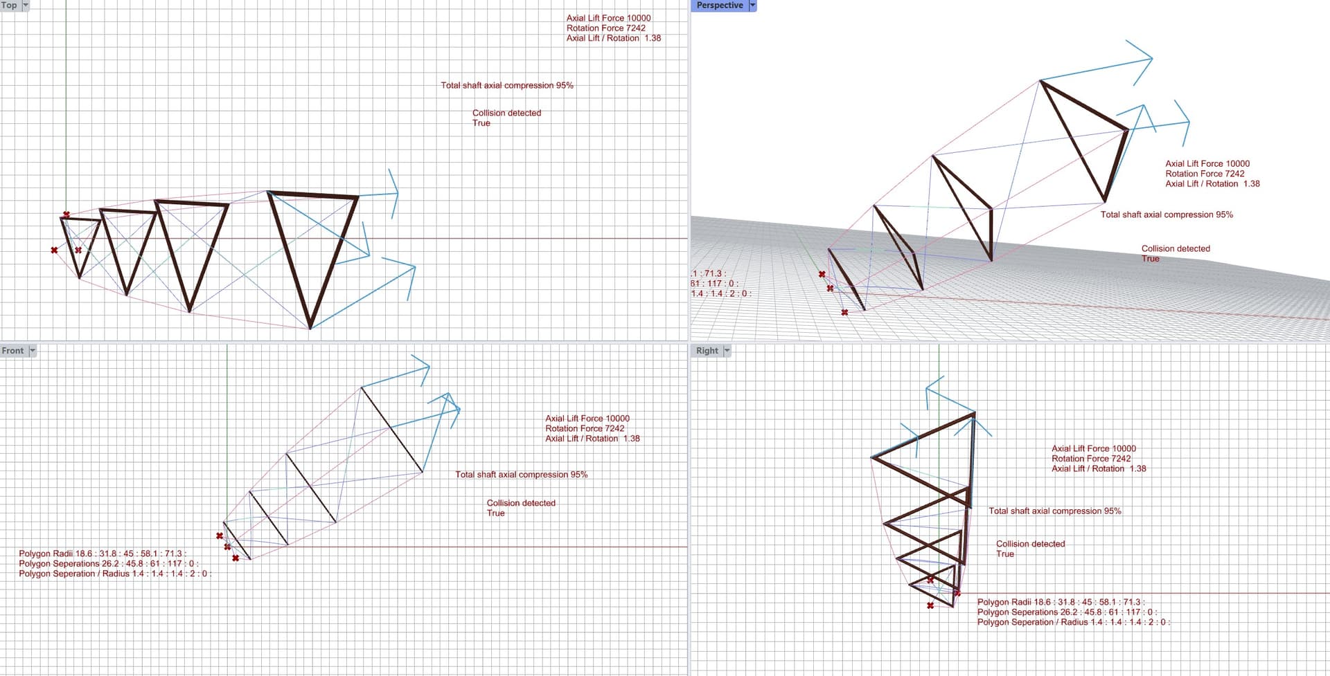
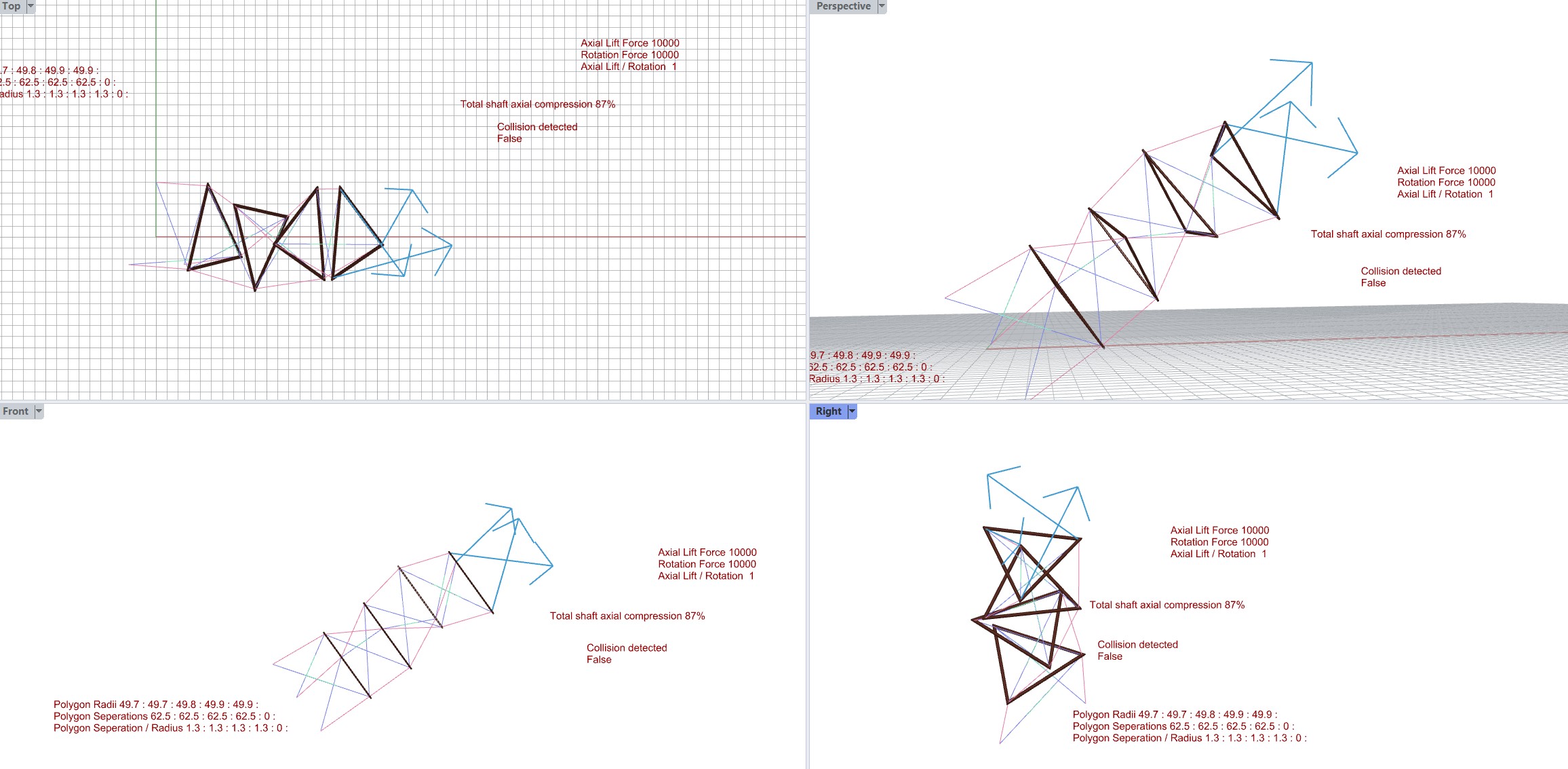
So having trailing lines in the mix with straight lines does initially keep the system from compressing
(remind me to upload the sim videos without motion damping - very boingy in cool ways)
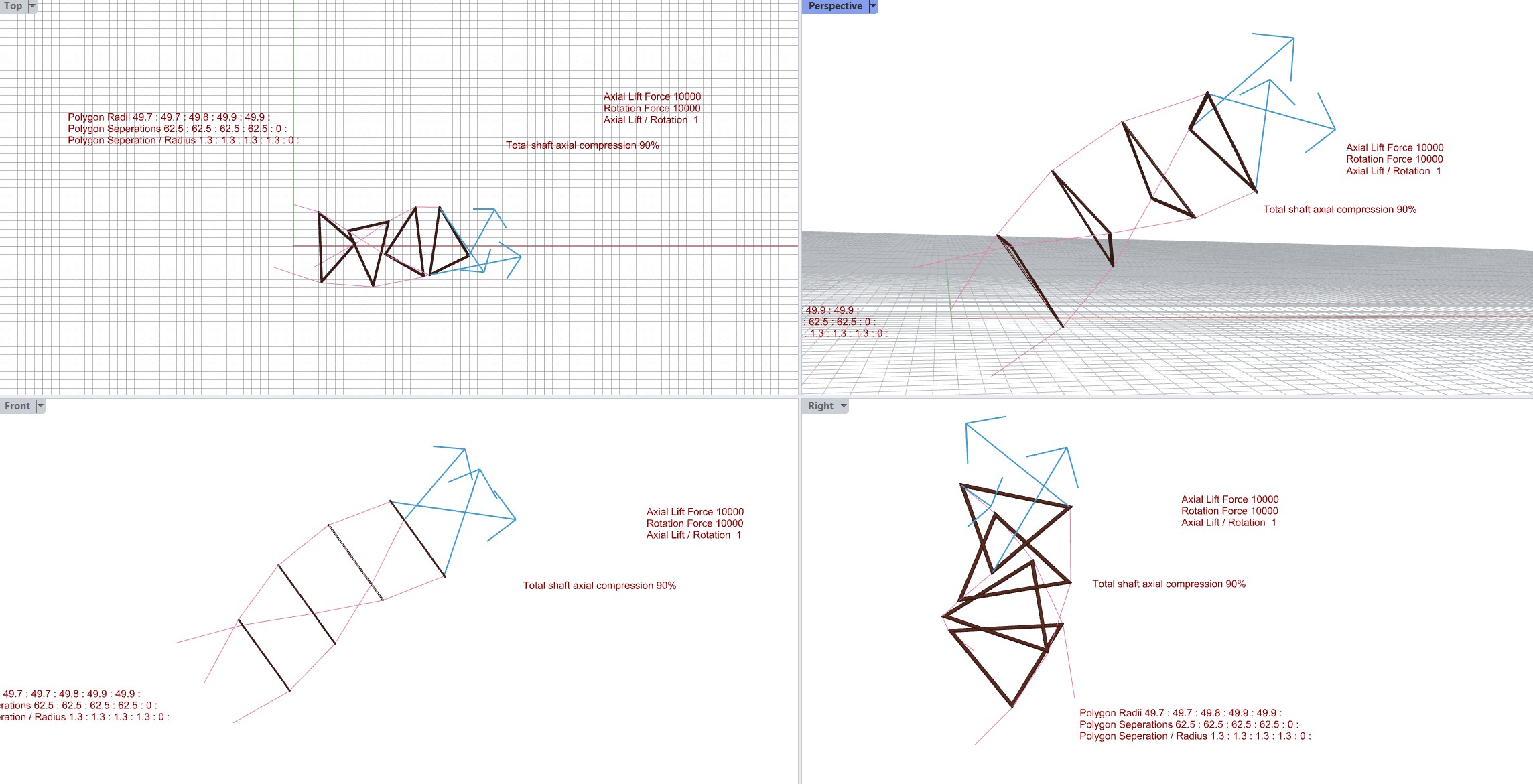
In reasonable line loading ratios (lift to torque) the extra lines prevent compression as compared to the TRPT systems with just straight lines
see the 2 following pics
I’ve made a demonstration video of the simulations showing the different effects
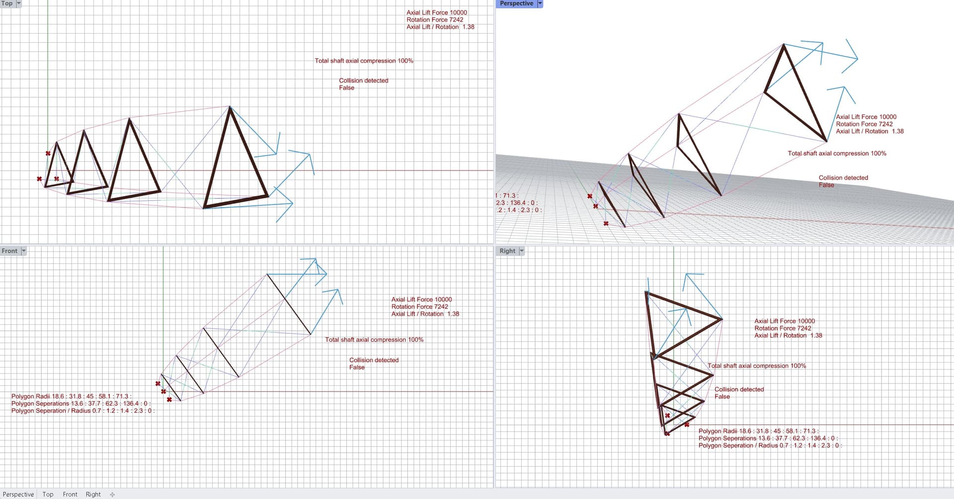
It looks like TRPT systems with straight lines between rigid polygon layers resist over-twist better than TRPT systems with straight lines and trailing torque oriented lines between rigid polygon layers
This work is most closely related to the rotary power transmission designs in
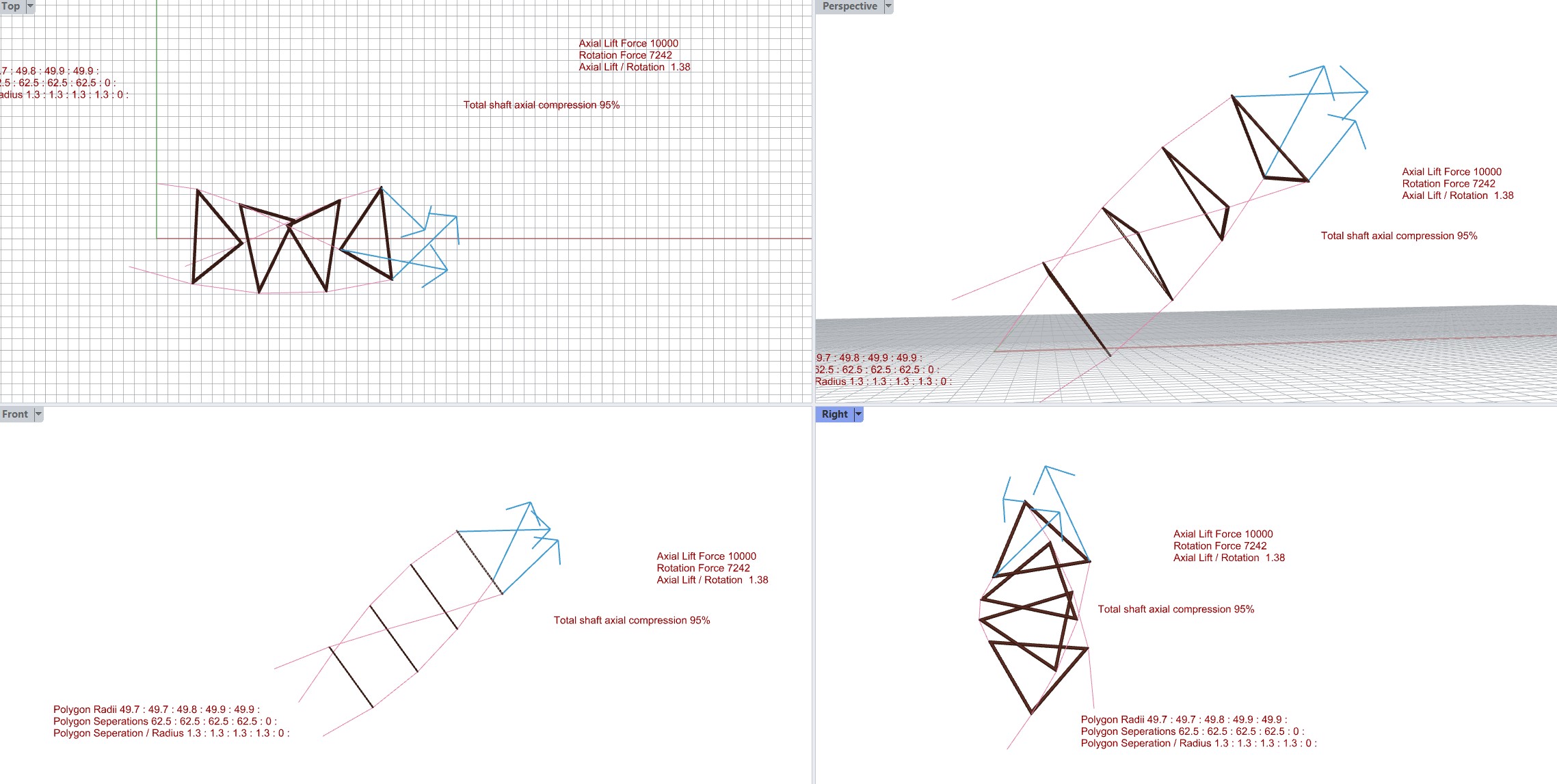
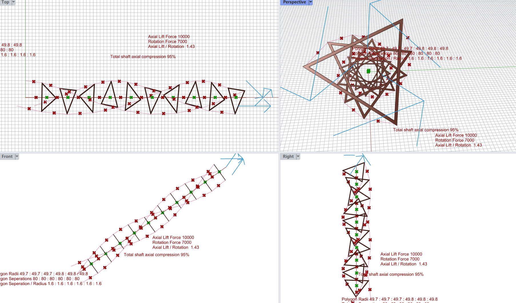
One effect which stands out for me is that when the rigid polygon layers are triangular …And the models are force settled… The triangles in the layers seem to become significantly displaced from their original axis in a spiraling pattern. You can see the overall shaft curve in the pictures in the previous post.
A spiral or bent spinning shaft like that will not be stable.
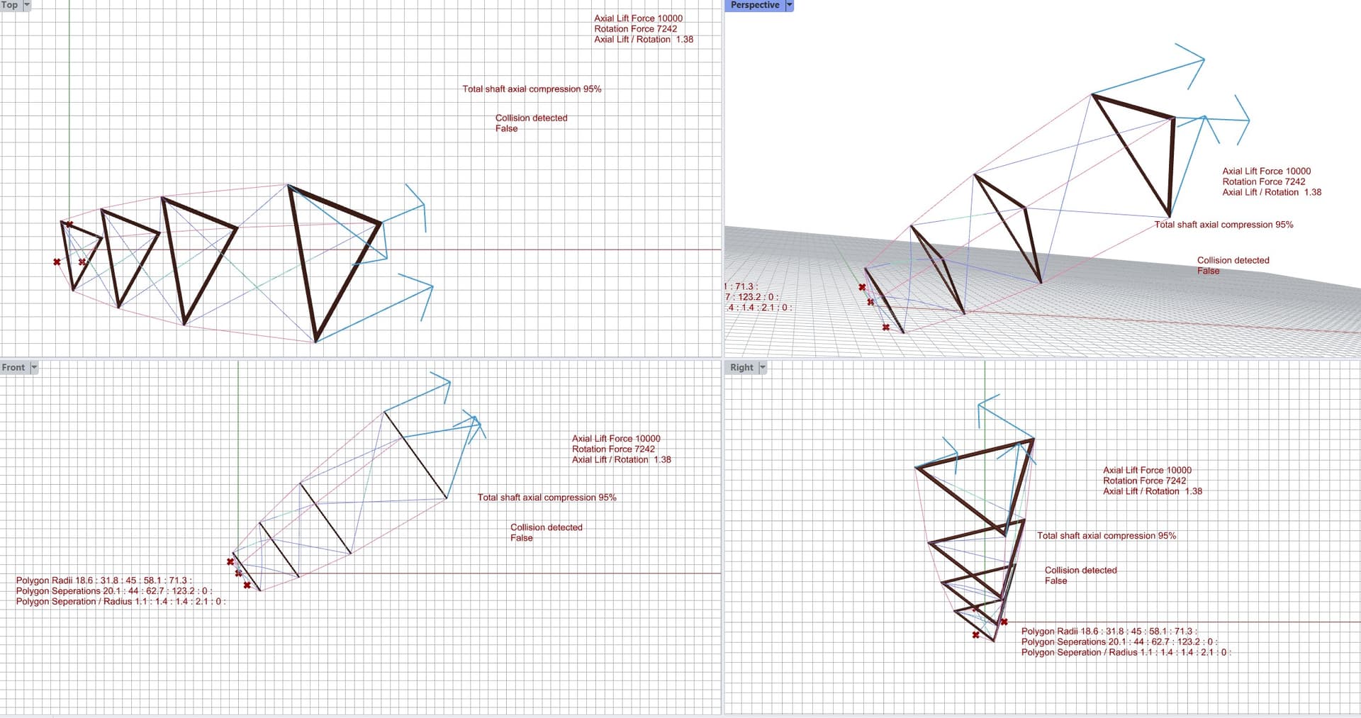
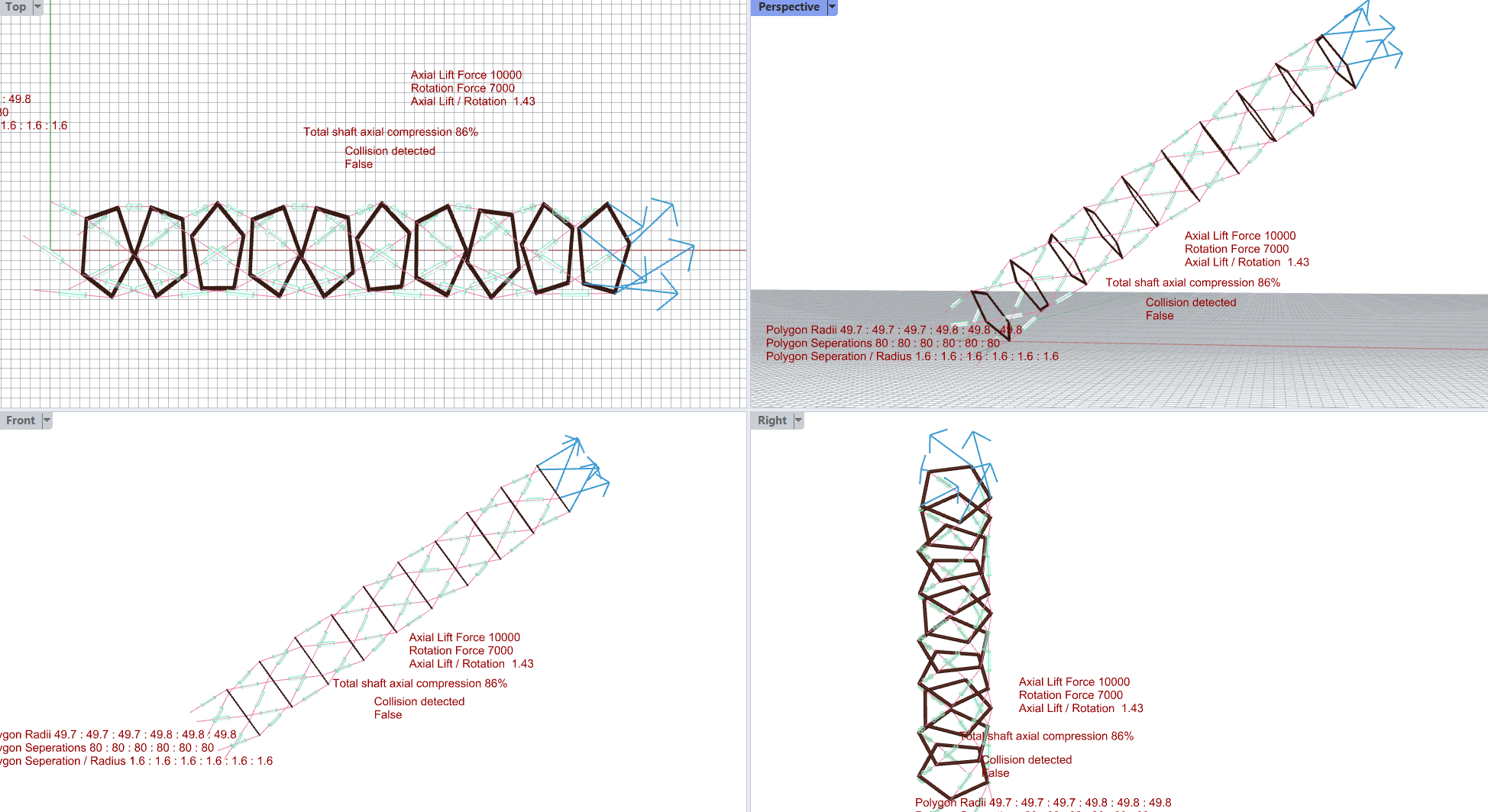
Adding 2 more sides to the triangle polygons to use pentagons looks to significantly smooth out the resultant deformation…
This similarly tensioned & torqued shaft appears to have less torsional deformation.
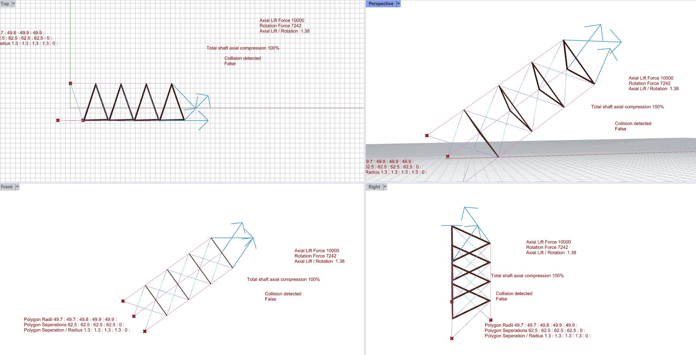
Seems like I am wrong again and fooled easily by optical illusion.
The centre of the triangle volumes is right on the centre line. also
I measured the average of the centre of the tx lines. The average point is basically right on the centre line. = No deviation of the triangles
It may not be so inherently wobbly …
I don’t know if you consider this? If your using multiple tethers to form a shaft then you might want to take a leaf out of rope/ cable makers hand book. Is there a way you can take all those torsion forces and consolidate it into a solid shaft? I know when twisting rope it tends to like to bind up on itself. This would all so make for a stronger tether. I see no easy of avoiding torsion forces so there must be a way of getting something better out of the situation? Medieval rope-making in Visby market - YouTube
It reminds me of torsion spring. It just about find a way to absorb those forces to achieve the desired results. In effect have it connected to a bike wheel. With it splayed at the bottom, tort at the kites attachments.