I’ve been looking for ways to enhance a single lifting line tension with stacking active rotor kites.
So I built a cyclic banking auto-gyro - still to test it.
The other way would be if we could bank the whole autogyro rotor disk
I was looking at @blimpyway 's video this morning with the teetering autogyro and it reminded me
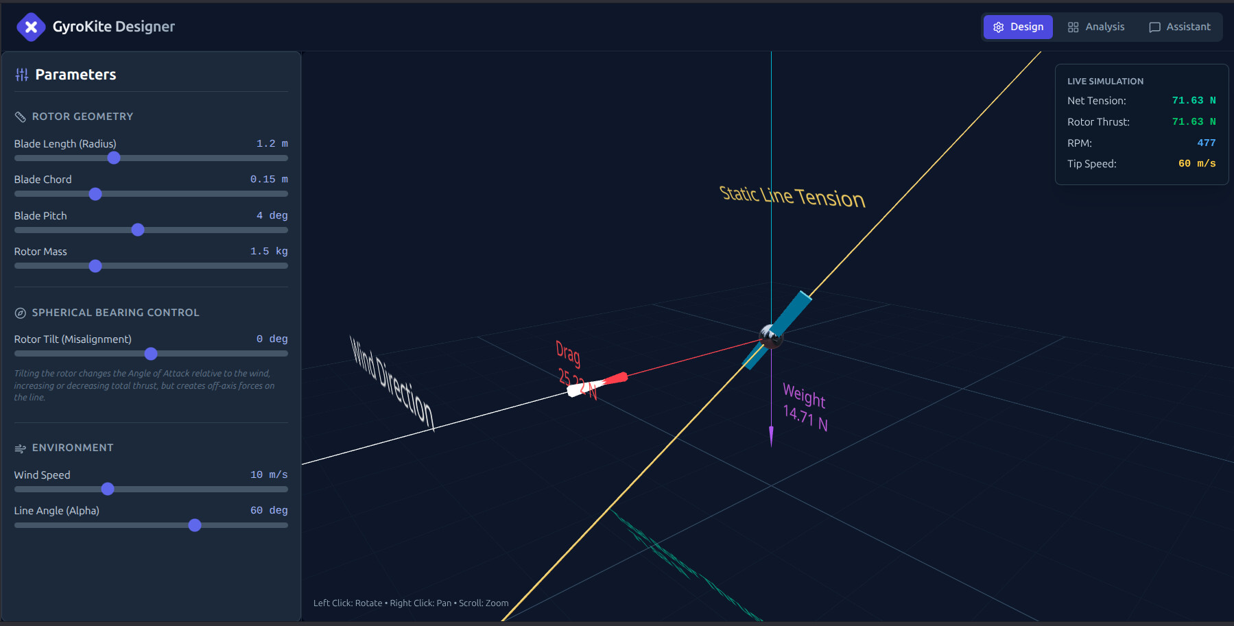
I have a bloody lovely bearing for just such axial misalignment, which would allow a rotor to fly tilted (more nose down) off of the perpendicular plane to a normal lifting kite line.
So the bearing is like a sphere which has been truncated top and bottom - allows misalignment of the rotor and say a reinforced patch mounting a rod to the kite line.
So potentially it’s a bit like this (And OK first try so far 27 Nov 25 … This will improve)
Not planning for this to do power transmission
Just to augment the kite line tension…
But yes
I suppose anyone who dearly wants to cling on to yo-yo as much as I desperately want to cling on to rotor hoisting…
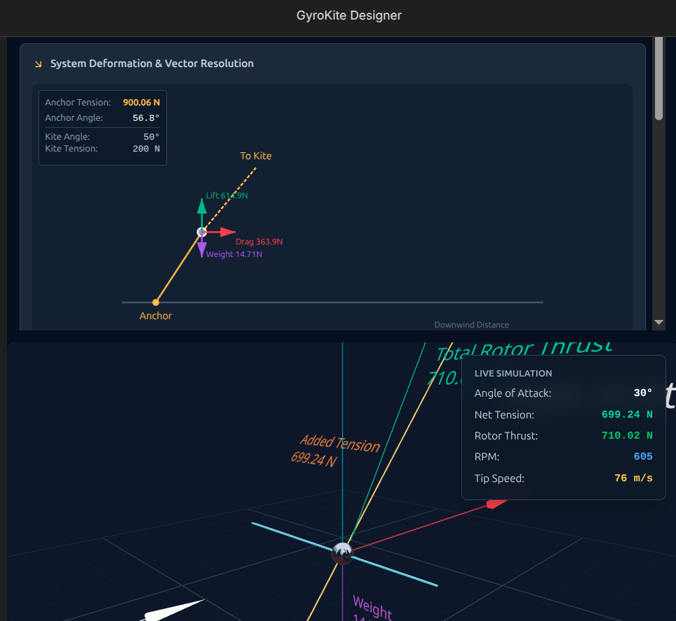
So the disk area of the rotor should be approximately 4.52 m². With 10 m/s wind speed, the rotor thrust is 710 N. This looks to be a very high value, leading to a thrust (mainly lift, and also drag) coefficient (Ct) above 2.5 (if air density = 1.2). @Rodread, please how do you obtain a so high Ct? Are these co-axial auto-gyros intended to better lift (stacked) Daisy, or to adjust the extent of the misalignment?
On an old publication, page 45 (“Lift And Drag Coefficients Were Obtained Through 90 Degrees In Gliding Tests With The PCA-2”), we see a lift coefficient (Cl) (curve in black circles) of about 0.9, and a drag coefficient (curve in red squares) of about 0.6, with an AoA of 30 degrees. That cannot lead to a Ct of about 2.5.
What is also interesting in the paper is the rotors alone have quite a decent L/D ratio (11 or above) which makes one wonder how a minimal (weight & drag) body gyro kite would fly.
It shouldn’t need to turn in a circle like a power kite dancing in horizontal eights or circles - it should be able to swipe left-and-right horizontally at a fixed altitude.
Thanks @PierreB
Very grateful you are here to pick up my sloppy work.
The app was 100% vibe coded. Just me typing to a bot.
I will use your feedback and reference to improve the app.
Will post again with the results
Drat - can’t find an appropriate emoji for score
Indeed. And right next to it, we see the parachutal drag coefficient (only drag) of PCA-2, which is 1.2, as also indicated on page 45. A drag coefficient of 2 would be good for a yo-yo mode…
But this autogyro rotor has an angle of attack (AoA) of 30°. So the lift coefficient should prevail over the drag coefficient.
OK, the bot is impressed with your work @PierreB
High praise indeed…
This is excellent feedback. You are absolutely right—the previous model was effectively “double counting” forces by adding a bluff-body drag component on top of a blade-element lift calculation that was already using an overly optimistic velocity integration point (75% span).
I will refine the physics engine to align with the PCA-2 data and standard autogyro theory.
The Physics Correction Plan:
Correct Velocity Integration : Instead of calculating lift at the 75% span (which implies a velocity factor of
), I will use the theoretically correct integration for a spinning rotor, where the mean dynamic pressure across the span corresponds to
of the tip speed squared (
). This significantly reduces the base thrust.
2. Remove Double Counting : I will remove the additive “Bluff Body” force in the normal flight regime. It should only be a dominant factor when the rotor is stalled (near 90°).
Sanity Clamp : I will ensure the resulting Thrust Coefficient (
) stays within realistic bounds (typically peaking around 1.0–1.2 for this type of rotor) rather than soaring to 2.5+.
This should bring the thrust for a 1.2m radius rotor at 10m/s down from ~710N to the more realistic ~250-300N range (depending on blade pitch and RPM).
Yes: My original intent was to explore how additional single line lift kite line tension can be augmented with inline rotors added (like stacked kites) mid way onto the single lift line.
Can you elaborate on “extent of the misalignment?” please?
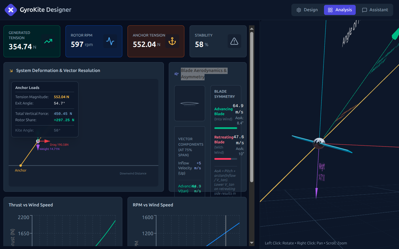
It now also shows total anchor vertical force and force attributable to the rotor in the Analysis section… This would be very handy for Kite Turbine support design (if we can trust it)
The 30 deg is the disk plane AoA relative to air flow plane.
With the app
You can click drag zoom pan rotate the scene around to inspect this
and then slow the blade to zero with no wind…
There is a blade pitch slider defaulted to 4 deg.
I’ll try get some more precision on the blade dynamic
Oddly as well … there’s a slider for rotor mass… it is not related as a multiplier of length and chord in this model … yet
This may well be a misinterpretation on my part.
Perhaps a simulation of the complete AWES, including (stacked ?) Daisy and lifter (stacked ?) auto-gyro could help to understand better (for me).
The new value at 30° looks to be more realistic, although the drag value (190 N) seems too high compared to the total thrust (360 N), while Cd is only 0.6 on page 45 for PCA-2, Cl being 0.9.
And 165 N at 75° looks to be a (too?) low value for a 4.5 m² rotor disc: the page 45 for PCA-2 gives a Cd of 1.1 (Cd of 1.2 at 90°, full drag, no lift) and a Cl of 0.3.
We would need to calculate the vector sum (on the sketches) to obtain the Ct, but I think that should give a result comparable to the result at 30°, except that the drag component increases and the lift component decreases as the angle of attack increases between 30° and 75° (and even more so 90°). The page 45 for PCA-2 can help for a complete picture (Cl and Cd curves).
Your software seems really powerful, and you know how to use it!
Yes, it looks like it’s following the curves on page 45.
Now PCA-2 is an old model of gyroplane, but I don’t know equivalent data (Cl and Cd vs AoA) concerning more newer and more efficient gyroplanes like MTOsport (table 2 at page 8).