Nice graph Rod. Not that I’m staying on-topic with this question, but getting back to the windswept island lifestyle, do you speak any Gaelic? (I’m going to pre-guess the answer will be “a wee bit”… ?)
Tha mi seachad air a ’chiad ìre ionnsachaidh
Gur math a thèid leat air an eilean ùr agad
1 Like
I reckon the tension readings can be roughly corrected by removing 2kg and multiplying by ~0.77
Thanks for this indication.
This remains a still surprisingly high value (about 600 N with air density of 1.3kg/m3) _ far higher than the axial force on a HAWT (about 320 N)_ considering the 11.2 m² of swept area and 7 m/s of wind speed. Daisy pulls strong!
I remember with only 3 blades the power could reach 1 kW and more. With 6 % efficiency (= power coefficient (Cp) ?), that had should lead to a very high wind speed, something like 14 m/s. But perhaps this speed was achieved during gusts…
Is it possible that the efficiency was higher than 6% (with 3 blades) and also perhaps 13% (with 6 blades)? Perhaps these values vary according to the wind speed.
1 Like
I would expect the tension readings to be higher than the thrust generated by the rotor. The lift kite, or in the most recent test the mast, will provide additional tension.
The peak power was experienced through a gust. The torsional flexibility of the TRPT means it acts like a giant torsional spring, storing and releasing energy as the system responds to wind speed changes. This can also result in power output spikes.
The efficiency/power coefficient is largely dictated by the rotors tip speed ratio. This varies throughout a test, controlled by the VESC. Ideally the Daisy will be controlled to operate at a fixed tip speed ratio that produces the maximum power coefficient, same as a wind turbine is. Daisy, on the whole, tends to operate at slightly higher tip speed ratios than the optimum. The optimum tip speed ratio for the 3 bladed rotor is around 3.5. Will be a bit lower for the 6 bladed.
3 Likes
The small TSR of 3.5 is due to the limited size of the windmill?
I would have a question to you or @Rodread or another person.
Should the lifter kite area be proportional to the rotor area, or not necessarily, knowing rotors provide also lift as soon as they are tilted?
I put a sketch below with only one rotor, then with several rotors to help to understand my question. Thanks.
1 Like
I can only qualify this answer in so far as we have tested, we have used the same lifter kite to lead stacked rotor turbines and single rotor turbines.
However, more lift to lead a stack, more reliably, is no bad thing, I’m certain we’ll want more of if for further scaling.
2 Likes
The changing TSR affects the rotor axial position and lift line tension …
Watch for the bucket moving… It holds a weight (bottom of mast) about a pulley (top of mast) to lift the rotor.
The whole turbine contracts axially in some conditions.
1 Like
I was really surprised this test was able to go ahead.
This was the state of the TRPT lines and knuckles on Thursday evening.
That was the mess left behind after the last test. Oops.
Luckily all I had to do to fix it was remove the broken rods and replace them. I didn’t have to untie anything. It was a very tight fit to get the last rod in each ring.
I was a bit concerned at the start of the weekend test that one of the lines looked to be longer when it was running… Doh. It was a PTO vs rotor misalignment effect I was seeing.
2 Likes
That’s looking bad. Do you know the cause?

Yeah, me in the test before.
This was how it looked before the test Luke.
The test went well after I sorted this.
Assuming that the TRPT geometry is unchanged, the ratio of torque to tension must remain constant. If stacking rotors, assuming each rotor contributes the same torque and thrust, the lift kite area would need to scale up proportionally to the number of rotors to keep the ratio of torque to tension the same.
2 Likes
I would put it down aerodynamic efficiency. The Daisy Kite blades are nowhere near as aerodynamically efficient as a modern HAWT, coupled with all the tether drag, brings the optimal TSR down.
1 Like
Thanks for the precision @Ollie.
Please do you think if it would be the same (ratio of lifter kite area / rotors area) as only the pull is used (in yo-yo mode), and not the torque.
I am experimenting (0.555 m diameter, and sweeping 0.24 m²) rotor(s) of gyrokite below a tiny lifter kite (a 0.2 m² parafoil). For now the angle of elevation of the kite alone is about 45 degrees; a rotor (alone, without body, rotating around the tether via a small hollow axis) below said kite has 35 degrees elevation angle (as for the complete gyrokite, the body providing low drag).
My question is: if I add several (even numerous) rotors below the same lifter kite (0.2 m²) their elevation angle will be the same (35 degrees) or not? I guess the reply is likely not but I am not quite sure. Thanks.
Roddy has anyone ever said you look a bit like “Dr. Zachary Smith” from “Lost in Space”?
“Have no fear, Smith is here…”
Woop Woop
The results from the testing on 16th May were up another couple percentage efficiency notches on last time.
Noice!
15.8% (AWES frontal swept area style efficiency)
13.8% (sensible world wing swept area style efficiency)
Averaged over around 1 hour 10 mins of testing
2 Likes
Considering the test as a whole was so jakey, wobbly, jumpy, starty and gusty…
Breaking the results into 1 min averages yields this very spread performance story.
Efficiency vs TSR
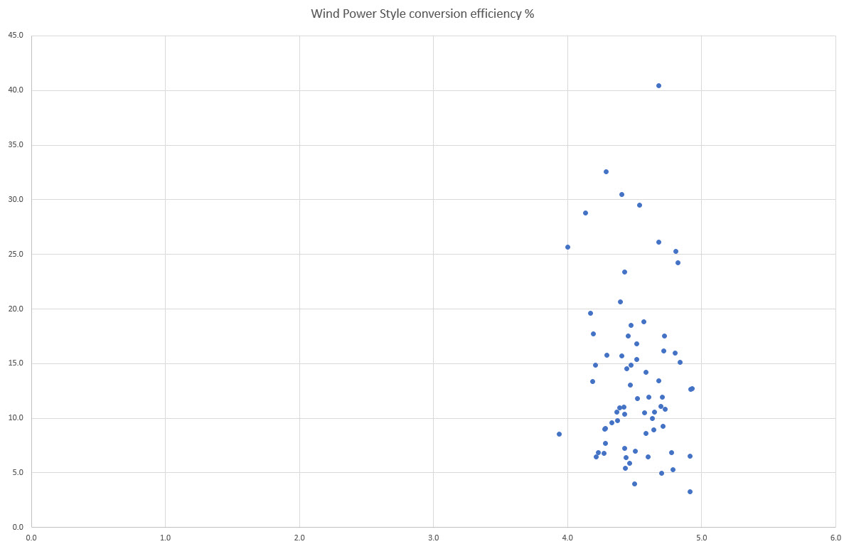
This shows where sometimes the control must have been much better matched to the conditions.
It seems fair, given the poor control methods, to pay some attention to the higher end performance (not the peak values)
Dunno how open to suggestion you are… but, to me, this section has the look of a power curve
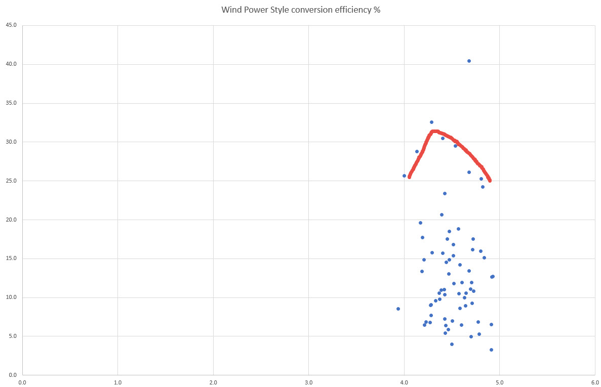
Also, I’d shift the graph to the right a bit, this is using the rpm reading from the controller for TSR calculation, The power meter consistently reads higher cadence.
Maybe not too far right as the wind also reads a little lower in the lower down controller anemometer…

Should say swept area 11.2m2 to check
1 Like
Out of curiosity:
- the swept area is just the area of the doughnut, and not a circular area like a HAWT?
- At what altitude did you measure wind vs the altitude upper/lower of the swept area
- AWE conversion efficiency vs wind power style?
This info would provide us better means to assess power output accurately. You are sharing so much already I wont hold it against you if you dont feel like sharing all these details.
Nevertheless the numbers are pretty impressive!
I would think a power curve plot would have wind speed on the x axis, rather than TSR?
1 Like