Now I feel bad about making you do that. Should have made some tests myself first.
Does the wobbling / tilting you showed first matter?
The folding up will happen when the tension is too low and the line length is too long. (I predicted this but I don’t think it’s on record anywhere.) I do believe it is different from the flipping of the simple torque ladder as with a counterrotating helix the sticks should be better held in a plane perpendicular to the shaft.
I don’t see the video as conclusive evidence that this OTS variant doesn’t work. But I should do further testing myself. Do you have some test parameters I can use so our results are comparable?
Omitting the counter-helices would make braking from the ground impossible, wouldn’t it? One would probably want to have that.
Anyway I did think you’d find it superior one you tried it. So you’ve proven the point that it’s not so simple and I’ll shut up. Thank you for trying!
A rod triangle with the triangles rotated 60° ( david’s star ) and four lines on each edge (plus maybe lines connecting the edges of every other triangle parallel to the shaft) could be considered a combination.
TAS - Triangular antiprism shaft (Took me some time to look that name up)
It is not that the “cutting corner” variant does not work - it is just significantly less dynamically stable - which is why I decided to not use it. Happy to see you do more testing!
Test parameters:
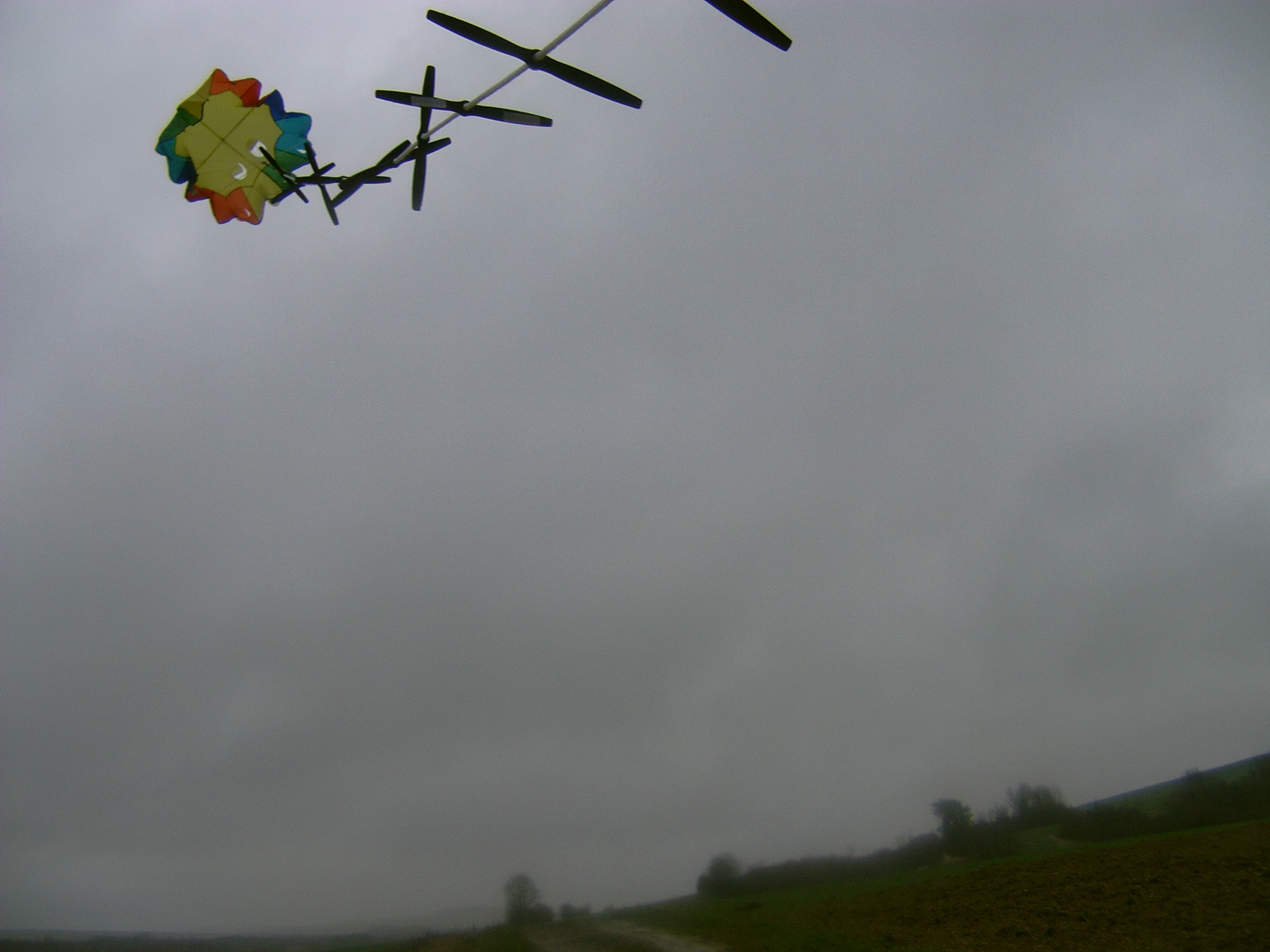
The rods in the video are 2 feet (610mm) long and 0.2 inch thick (5mm)
THANKS to moving back to Europe I have switched to metric in the meantime (500mm * 5mm) hence I did not need the old OTS anymore.
Spacing between rods is 2/3 of the length (~400mm for the 2 feet) - this is slightly below the “edge to opposite edge” distance (1/sqrt(2) or ~0.7) of a regular tetrahedron - keeping the tether length just a little under the rod length - preventing them from “flipping through” (you can see them touch the other rod in the video). I have not tested other spacings - this just seemed right
The counter helices are not involved in braking - that’s what you technically do with the two “work” helices. I have used them however to speed up the rotor - when the starting torque of the rotor was to small due to low pitch.
Thanks Olivier.
Always good to see someone more insane than myself.
Hardly going to get any power out of that.
I guess there is torque transmission along the line
This Savonius-like is sold 289 euros for the first contributors as indicated on the linked page, that for something like 10 W at best. Because we speak about gadgets probably this crank generator would be lighter, cheaper, less cumbersome:
Not sure I should be uploading these videos here ?.. taking up forum hardrive space…
model still improving… but not convinced about the rotation forces on the top ring…
you can see here compression on the rings and tension in the lines most tension on the sides going to the underside and on the side closest to us pulling toward the sag
This is likely the fault of the swivel not the rope.
I’m not going to say a rope on it’s own is good for transferring torque - definitely not - but a tiny swivel definitely won’t help it.
The drag on a large inflated solid shape shaft would be hideous. Torsion and torque in inflated beams for kite twisting in AWES was studied quite early on in one of the large fundamental PhD reviews (sorry on phone can’t remember the one)
What’s the line drag in your system (also @someAWE_cb) ? A shaft only gets pushed downwind by the wind. It’s not obvious how that impacts rotation much. You have lots of lines going much faster than the true wind.