That’d bend too easily I think. You could add a rigid spar.
1 Like
You’re right in terminology… I was referring to downwind loading “dragging” pulling the system down. This will be huge in the inflated beam necessary for decent power transmission.
An inflated beam shape is hard to maintain. An unsupported bent shaft is hard to transmit through. Multiple linked short sections can maybe avoid buckling.
Skin drag on the rotation will still be a thing too.
Thicker lines are great for tensile transmission in terms of power to drag. Tubes not so much.
As for drag in torque transmission lines Daisy style… The coned shape allows lower lines to be closer together which means they’re not dragging through so much air…
By using more kites upper and fewer lines lower the tension on lower lines really helps efficient transmission
1 Like
The classic paper in question was of course …
An Engineering Methodology for Kite Design
by Jeroen Breukels
Pages 89 and 117 onward show the inflated beam bending and torsion studies.
Plenty of detail on inflated beam torsion , bending , wrinkling formation, elastic behaviour and buckling.
I think one of the main points is …pressure is limited by materials.
2 Likes
This guy from twingtech knows about inflatable stuff:
Worked on this whole Tensairity thing.
I personally believe that a shaft inflated with high pressure wrapped in tether helices is worth investigating. Just thinking about it I can’t find a reason why it wouldn’t work.
2 Likes
Love Rolf - a really impressive guy.
The latest Twingtec http://twingtec.ch demo is beautiful.
Their early experimentation involved inflated kites & structures.
I think they published quite a lot of data @Tom …
Is it as a torque transmission device you’d like to test this tech?
The TU Delft study mentioned previously
An Engineering Methodology for Kite Design
by Jeroen Breukels
is available here
https://repository.tudelft.nl/islandora/object/uuid:cdece38a-1f13-47cc-b277-ed64fdda7cdf?collection=research
Personally my favourite device for testing the potential of spiral wound, thin wall, torque transmission tubes is … as usual … a toy . . . a kids pop up play tunnel… Stand on one end … twist the other… very different deformations depending on if you twist with or against the helix.
Oh £&%$ I have an old embarrasing video somewhere…
1 Like
Tensairity is different from what I proposed. I’m not aware of anyone having looked into it, but considering how basic it is, somebody must have done it.
A bit hard to pressurize that. I’d propose a cut bicycle tube in a sleeve wrapped with cables or something like that for first tests.
Cables transmit torsion. There’s a benefit from having a (little bit) bigger radius. Cables are kept at the radius by the pressurized middle section.
Thanks for the link to the study.
1 Like
Rolf seems to no longer use inflatable (comprising Tensairity) beams for Twingtec. It would be interesting to know the reasons, even if you can guess them.
Try it
please give an honest report back
love to hear how it goes for you
1 Like
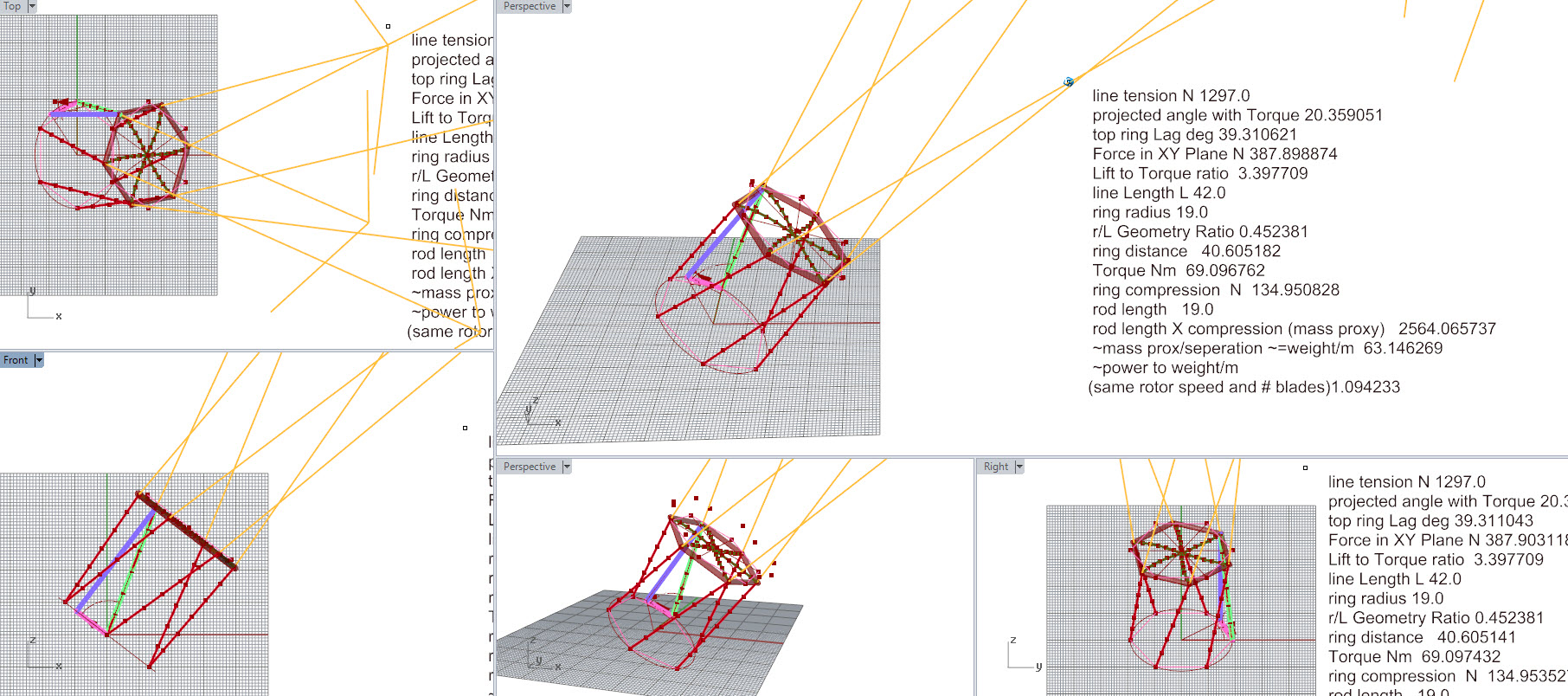
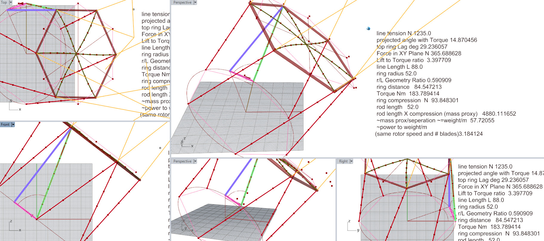
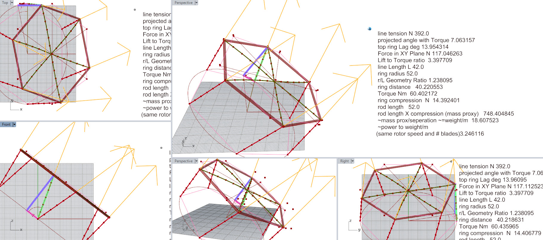
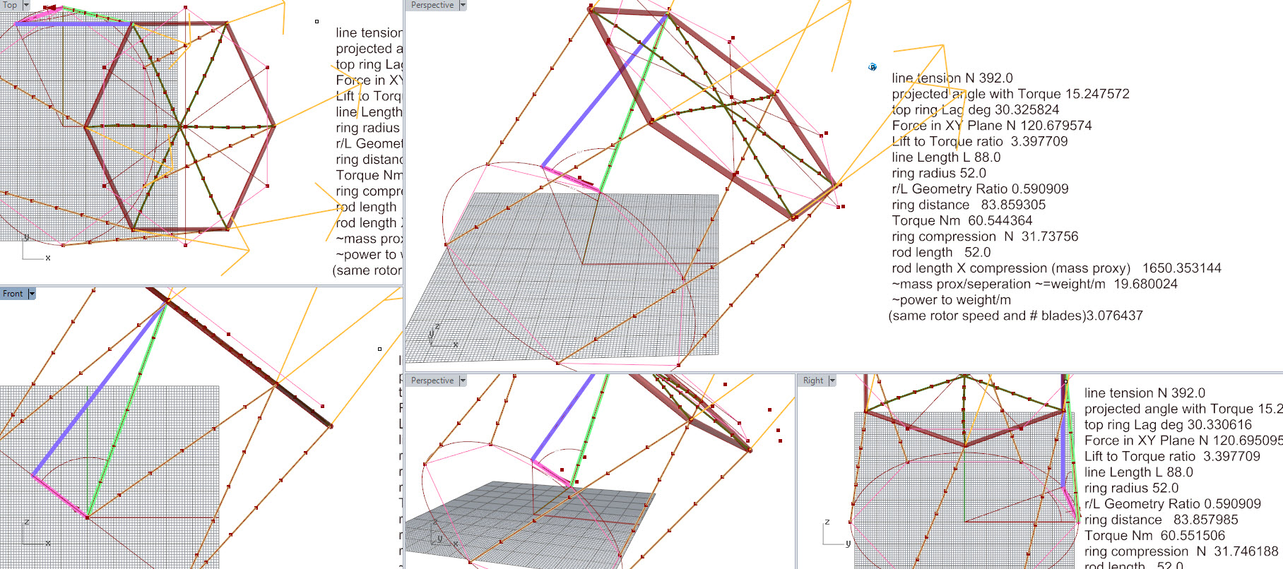
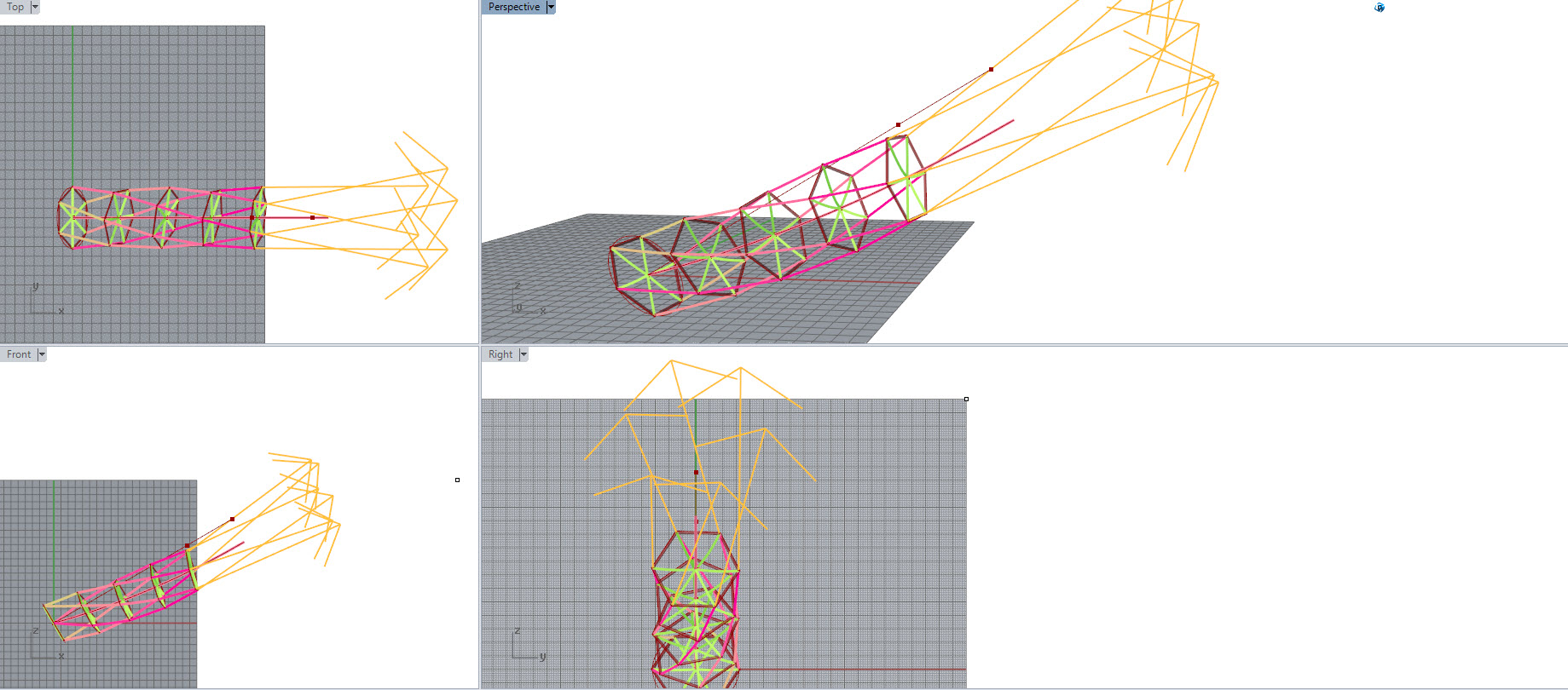
How to break the rings in a tensile torque transmission ring ladder set…
Best sim yet of the effects of line tension and lift to thrust ratio on ring compression and torque output
Ahhh had on some mistakes still… doh …classic types
yep the model was wrong… I’ve given a better try but still…
Hoop rotation sim compression angles straight uplooping.gh (77.2 KB)
definitely not quite solved on analysing the output…
tried uploading a wee vid but aparently too big.
Ahh crikey more mistakes…
2 Likes
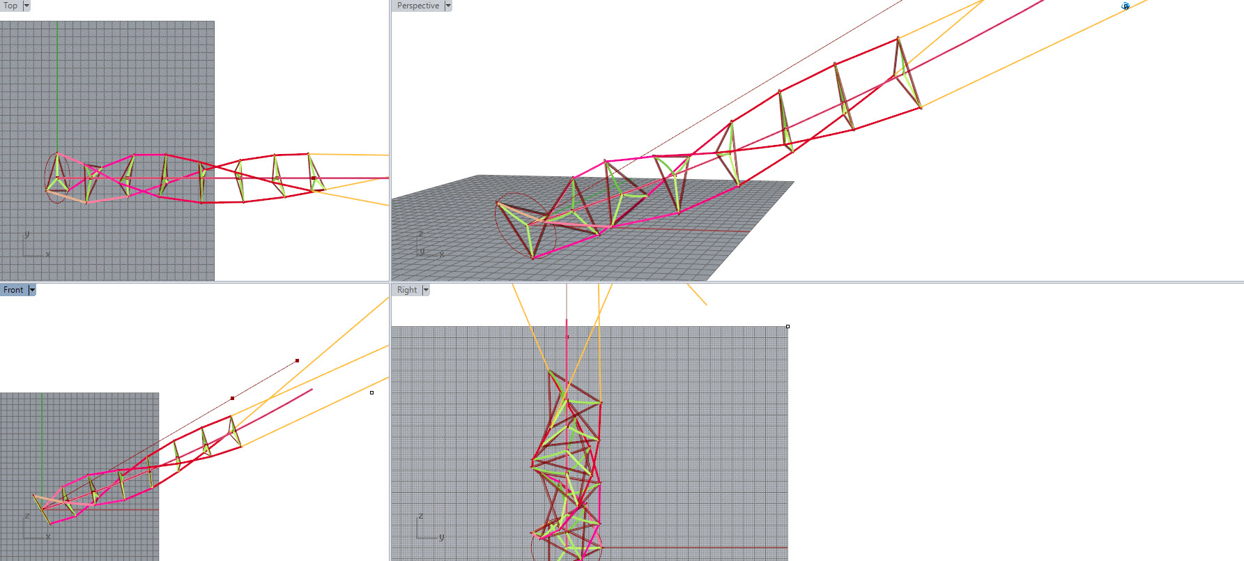
Oh at last… There were some right clanger mistakes…
Sometimes you just need to step away from the computer… take a walk and it becomes obvious…
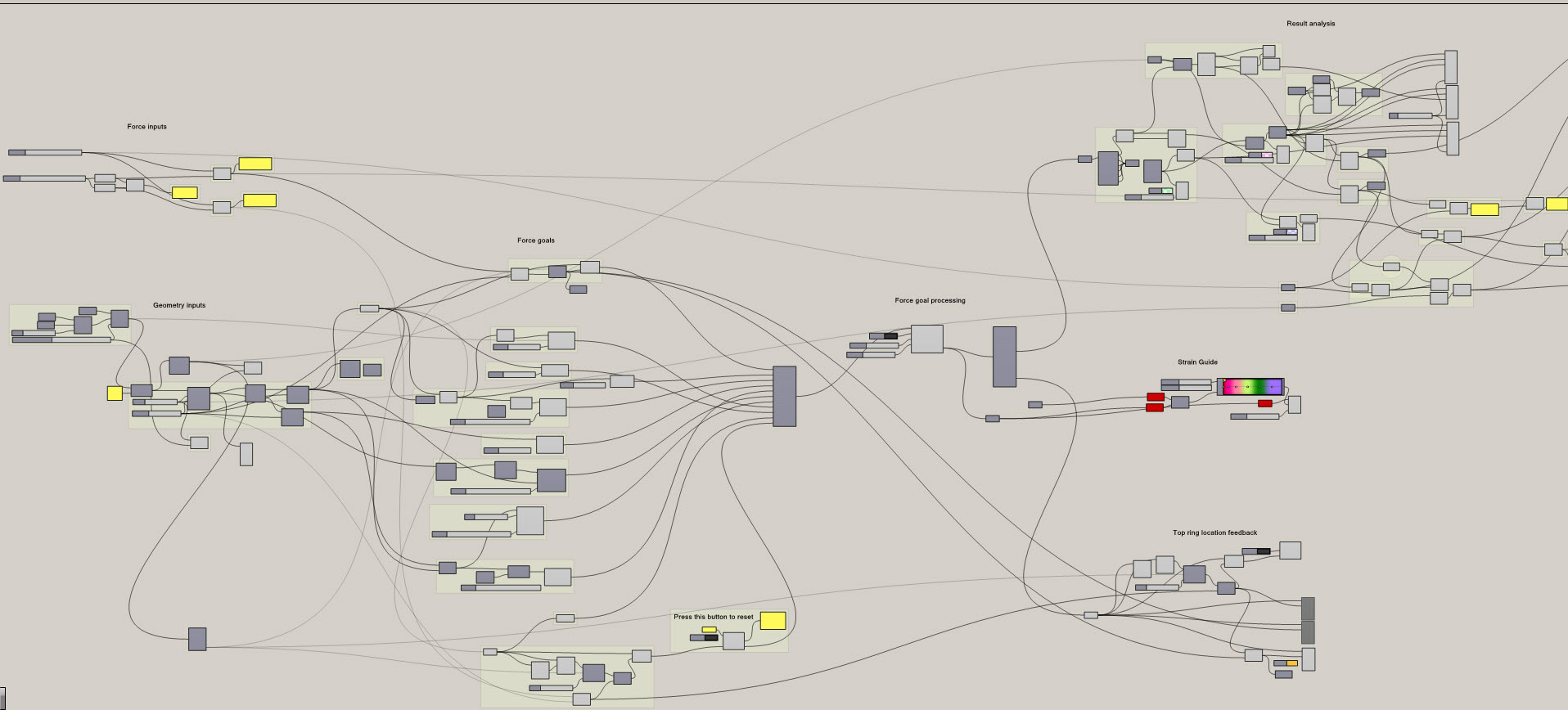
The .gh file for anyone with grasshopper
Hoop rotation sim compression trig input checked output.gh (78.0 KB)
1 Like

1 Like
Way back in the early days of AWES research… I’m sure there was a study which rightly pointed out that torque transmission over a rope (single line) was a very bad idea. Weight, compression, torsional rigidity, twisting etc being problems…
Q. Does anyone know what this study was? Where we can find it?..
Been looking for ages now.
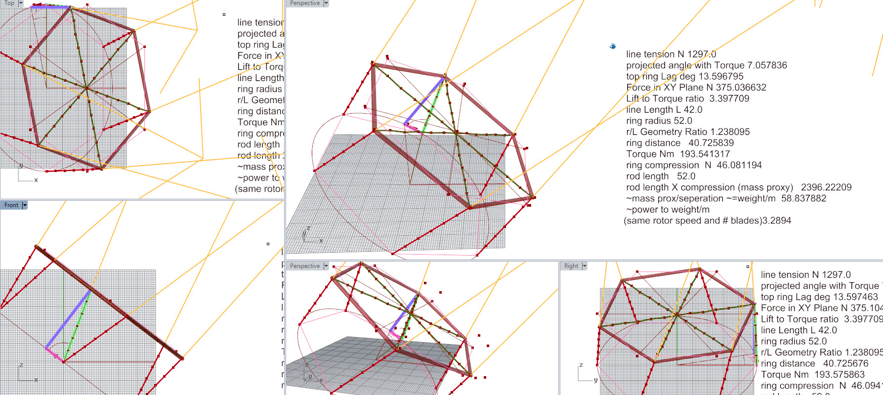
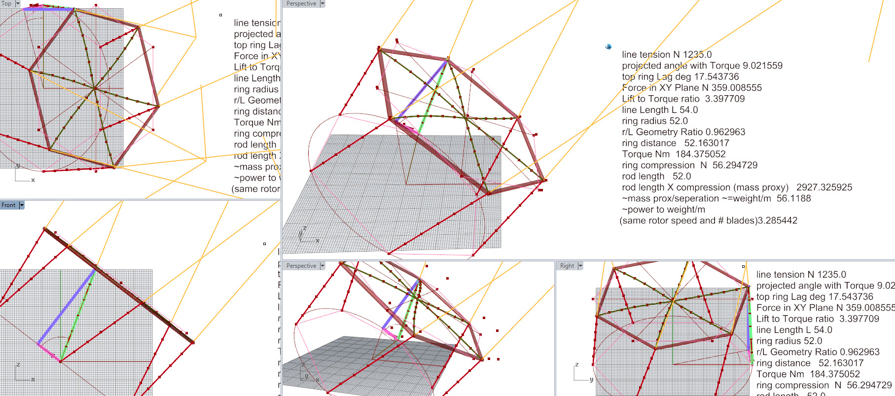
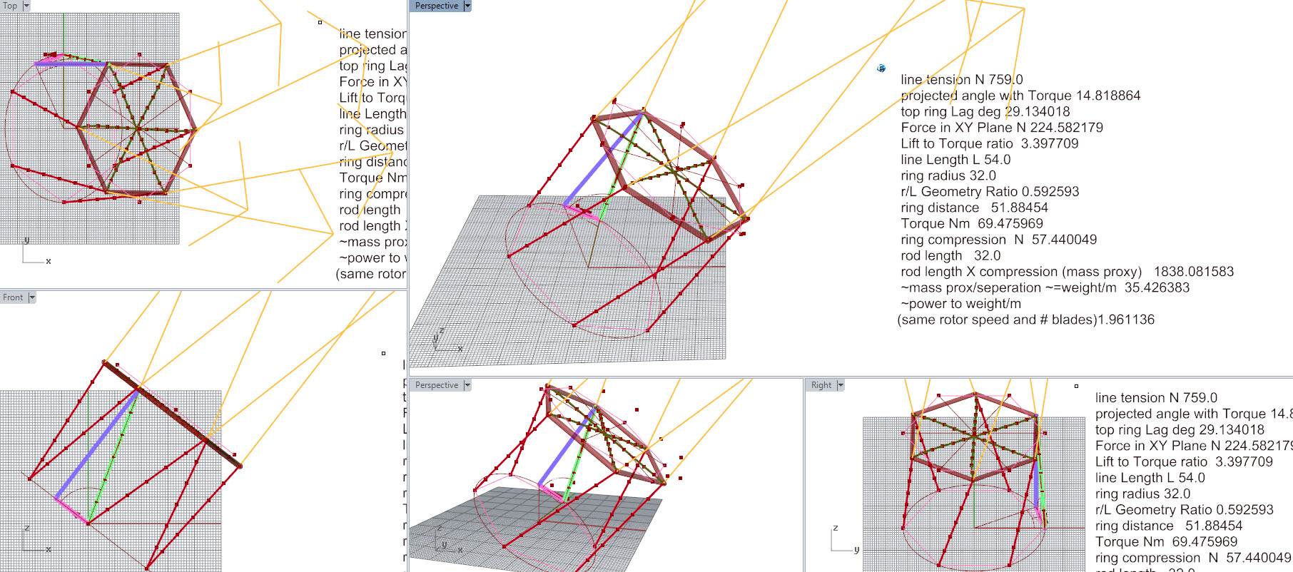
The .gh model is now much more versatile and accurate.
Seems to like heating up my silicon though.
Good to see the model has weight as more an issue higher up … physically not so great for implementation but realistic
1 Like
One further key point about rotary power over networked tethers… Line fairing is possible.
(@Ollie reminded me this week)
@Ollie has also developed significant analysis of the method which blows my tiny thinky capsule. It’s sooo sweet.
So line fairing is basically an aerodynamic sheath over your line. The cylindrical profile of a line has a very high drag coefficient ~1.2 whereas faired this drops to ~0.3 (correct?)
This AWES power transmission system is (uniquely?) suitable for fairing because the line lengths are so short, so no twisting is likely … and also because the line is always travelling in one direction.
I’ll have better scaling data (better model again) before the end of this week.
Could you explain why that is? I would expect a kite network to be easier to implement fairing for, as the lines might not be rotating…
The fairing will act as a vane, if it is free to move and orient itself correctly.
Manufacturing something light enough will be a challenge.
Hi @tallakt, yes sure,
So I was talking about the “shaft” part of a daisy kite here… hoop, 6 lines, hoop, 6 lines, hoop, 6 lines…
That’s as opposed to a lifting kite network…
Example of a rotary network
Example of a lifting network
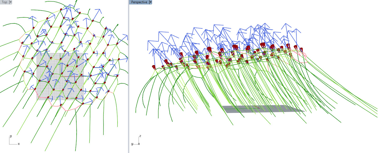
Example of a lifting network used to support rotary networks
A rotary network is a continually rotating set of 6 tethers (Could be any number >2)
Already demonstrated is how the tethers don’t need to be going through a lot of air really fast… e.g. The lower tethers (near the ground) in the videos are spinning closer to the axis (Set on smaller radius hoops(hoops also closer together)) than the higher up tethers going around the big kite radius.
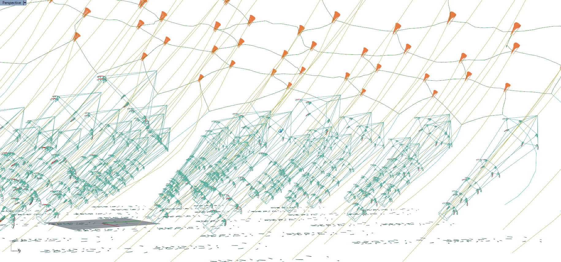
So on a rotary network, always going round clockwise from below… the lines will mostly be “seeing” apparent wind from their forward rotation motion + true wind vector … the true wind vector is likely a fair chunk less than the rotation motion. So a forward-facing fairing on the line will be mostly well aligned ± maybe up to 20deg.
The fairing can maybe be tuned to encourage line expansion radially away from the axis. This would consume energy… I think.
Fairing on a static lifting network would be harder as it has long lines and also has to face wind from any direction.
Any component moving over another component is prone to wear …multiplied by the frequency this would happen on a rotary part … Going to burn out rapidly. Do you see a need for a vane on the rotary part?
Have you seen the research on efficiency gains from fairing in AWES yet? Think it was in Storm Dunkers work.