I would transmit Peter Sharp’s analysis on https://groups.yahoo.com/neo/groups/AirborneWindEnergy/conversations/messages/24389, then @Rodread’s reply on https://groups.yahoo.com/neo/groups/AirborneWindEnergy/conversations/messages/24390
as they look to be relevant:
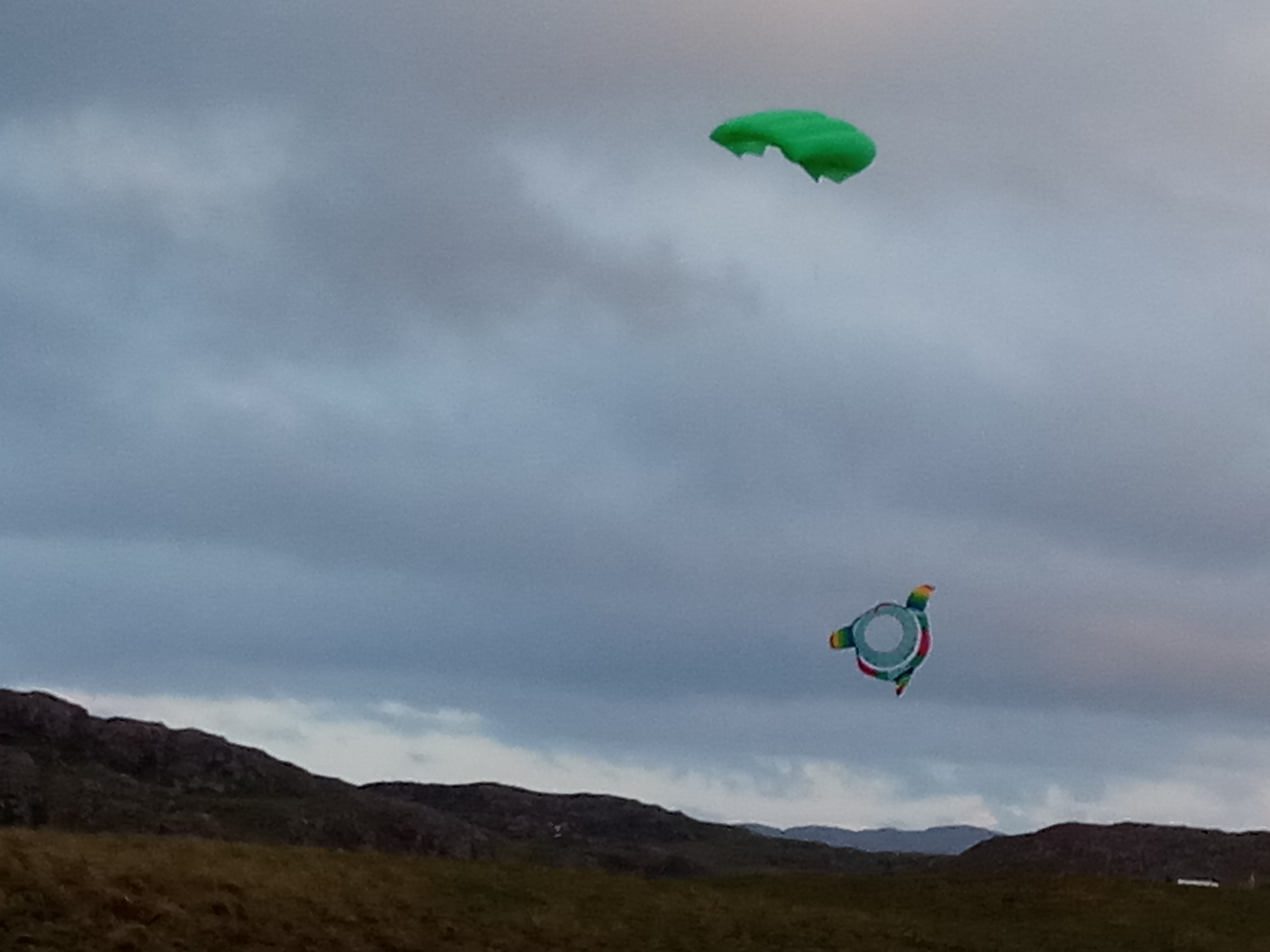
“I think that the Rod’s video showing the collapse of the torque transmission train of hoops may reveal a serious limitation of the concept.
The good blades on a large hoop produce a strong torque in a strong wind. For any such train of hoops, there will be a maximum torque that they can handle based on the tension between the hoops and the stiffness of the hoops.
The problem, as I see it, is that the train of hoops must remain under enough tension to prevent the torque from twisting the hoops relative to each other, or collapsing the hoops.
If the hoops twist much relative to each other, that will pull them towards each other and may also twist the connecting lines into a rope or start to distort and unbalance the hoops. So higher torque may require larger diameter hoops, or thicker hoops, or hoops spaced more closely. Those all increase weight.
What seems critically important is the ratio of the tention to the rotor torque. The rotor drag, along with the pilot kite, produces the tension required to transmit the torque. The solid blades on only one rotor seems to have produced a lot more torque than multiple rotors with soft blades, while also reducing rotor drag. So there wasn’t enough tension between the hoops, or the hoops weren’t stiff enough.
A simple solution might be to use a larger pilot kite to provide enough tension to match the increase in torque. But the hoops still might not be stiff enough. So I would think that the first step would be to replace torque with RPM so as to handle higher power. That means using smaller rotors that spin as fast as possible. That will increase the drag of the connecting lines, so there will be a tradeoff.
I think that basic indoor experiments need to be done to determine the relationships between the variables.
Personally, based on my tinkering with transmitting torque between hoops, my guess is that hoops cannot transmit enough torque, and that there will be a scale effect where the weight of the hoops rises faster than the torque they can transmit. So the concept, based on using hoops and lines, may be limited to small scale.
Doug’s use of a flexible shaft and small diameter rotors may end up being lighter relative to the power that can be transmitted.
PeterS »
"Hi Peter S,
Thanks for the comments on Daisy performance.
I agree and disagree with your observations and conclusions.
Yes there are serious limitations to consider in torque transmission capability.
Yes You can reliably kill a torque tube transmission by overtwisting or overloading.
Everything can break but let’s find out where in this case of this tensile torque tube transmission method.
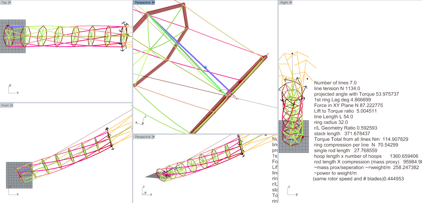
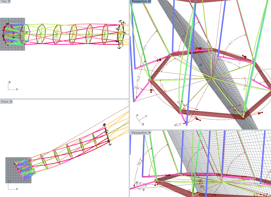
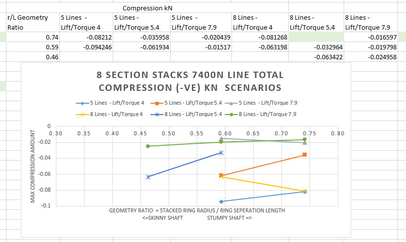
The twisted state, which kills torque transmission, occurs when any 2 consecutive rings are allowed to twist > 180 deg with each other. This may happen when a ring between 2 other rings is crushed (thus lengthening the gap between 2 rings) or when the geometry and tension balances are not within the workable range of a torque tube. e.g. too much torque for little lift on a tube with small diameter rings too far apart
So to avoid crushing rings, I’m willing to be wrong… but I think that’s pretty much down to limiting the torque you use, given the compressive capacity of the rings in your torque tube set. I had a current limit (analogous to braking torque limit) on my controller software but it may have been surpassed by the current handling in the motor gen FOC controller.
Speed is yummy, we love speedy wings. Lets have more fast please.
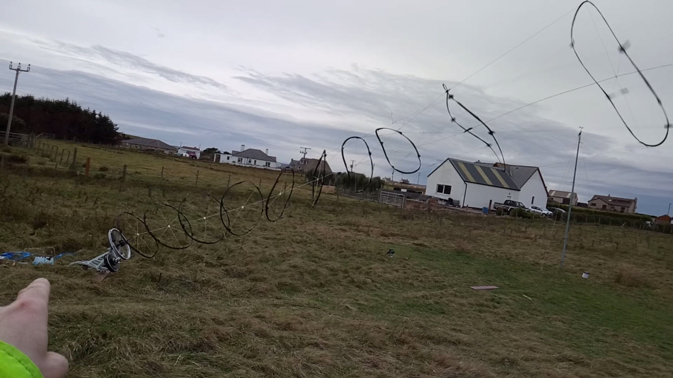
The other thing to ensure is your geometry is up to scratch. Mine wasn’t. Have a look at the 3 attached frames from the video where the torque tube collapses.
Frame 1.
A serious wobble has occurred. The loading is very uneven on the lines. The 8 lower rings (each with 6 lines between and set around the centre line) are totally out of alignment. The generator was allowed to wobble a lot and had a crank handle on the PTO wheel which didn’t exactly help.
The large ring (top right, lets call it “1st”) has 3 points of connection from the driver kites above… but 1st ring has 6 lines connecting to the “2nd” (next lower, left and down) ring. 3 lines are very tight on the 2nd ring, 3 lines are very retarded from the topmost small ring.
A messy centre line join can be seen as a black (Duct tape) lump near the centre of the 2nd ring… This is where the big snap happened in the end
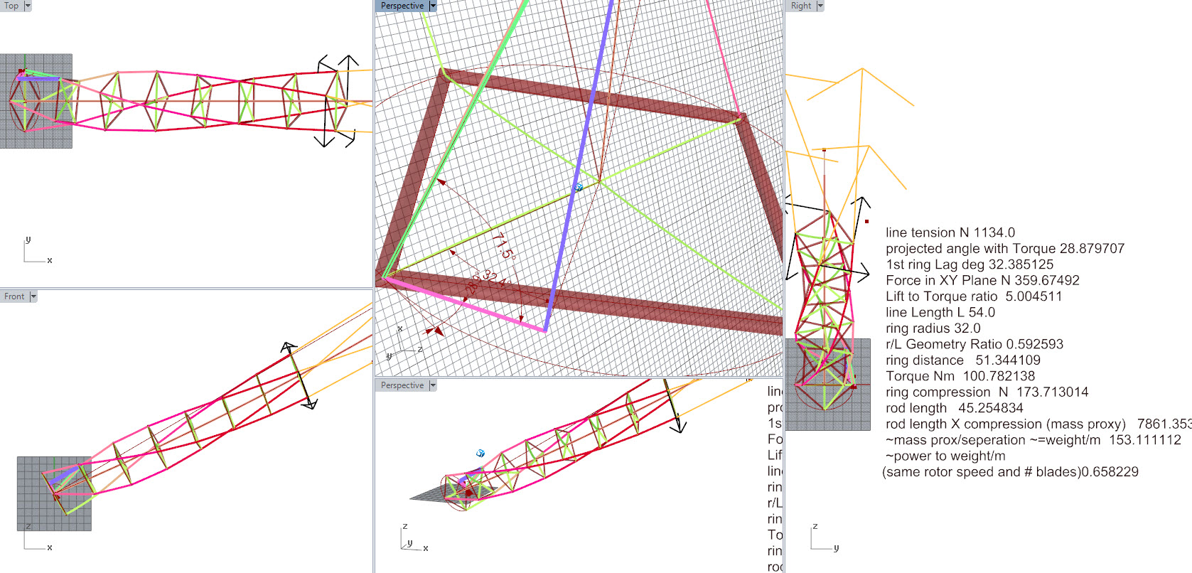
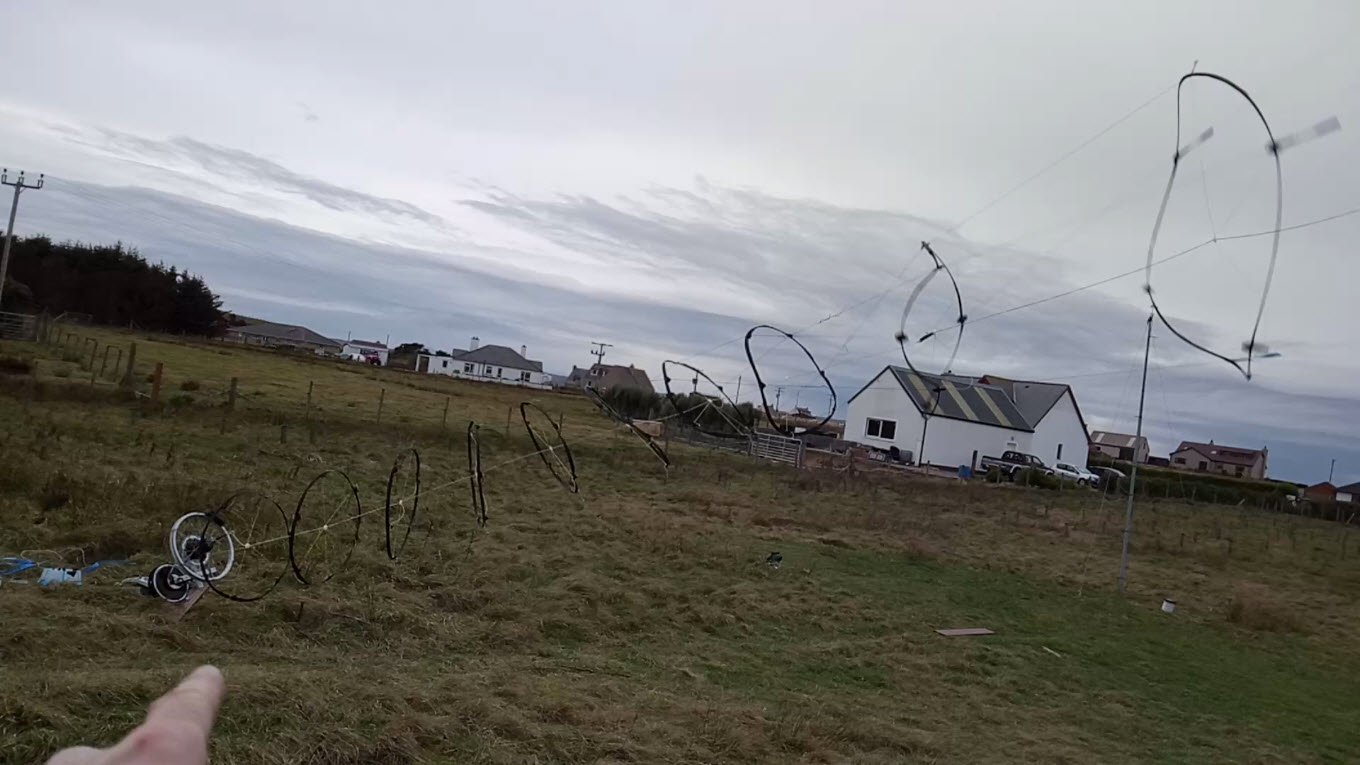
Frame 2.
Huge tension is evident in the rotor lines, the lift line looks a bit limp (I would like to try getting rid of the centre axial lift line by using tensile inside stiffening of the rings e.g. 1 method being with node to node lines, and / or node to second node lines)
There is not a lot of twist between ring 1 and ring 2 there is huge tension on those lines. the twisting is mostly in the next lower section >90deg twist between ring 2 and the topmost little ring. The line twist (effectively a pinch) means the capacity to stop further twisting is going down rapidly.
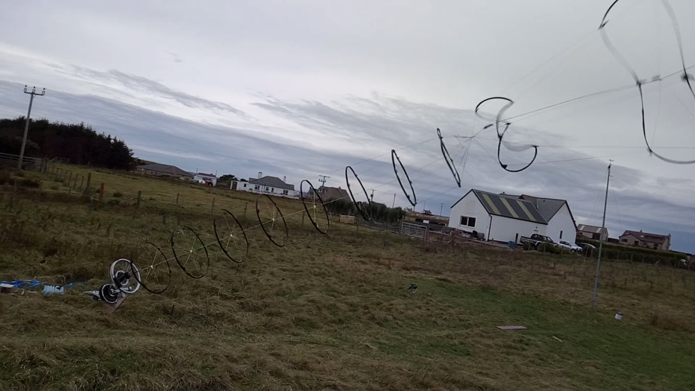
Frame 3
Oh my, that happened,
well it seems my crude generation control algorithm wasn’t fast enough backing off the torque demand this time… (previously it was as seen in the video about 15 sec before… you can see me @ now in the vid explaining how good it was… doh) maybe no slowing was evident in the appropriate time frame. Who knows, my data collection was shite. More shite at this point I hadn’t reinstated an overdrive button to push the PTO wheel forward faster than the kites… To be honest it was quite a relief to see the stack failing. This test was scary and there was nobody holding my hand.
I was looking for ways to kill the test. (walking the back line around 90 deg to stall the rotor is best)
Evident beforehand in the video is the degree of twist in the tube is high. In a way this is good. it’s running somewhere near an optimal if there is a good balance between the lift and torque.
The problem this design has is the relation L/D in the kite rotor, will not always be matched within the capability of the chosen geometry and torque demand unless you get right smart at reading the tension and line angles really fast… also controlling the wings a bit will help…
More driver kites may be better, presenting a higher number of connections will lessen hoop distortion, also low solidity was previously a problem… not so much on this occasion.
Power to weight this was 2kg airborne outputting 1000W
500W/kg is a very good start for a small system
Rotating a blade is inefficient, A larger rotor sweep is less so.
Speed is yummy. I wrote that before lunch. Still seems kinda logical afterwards."