I’ve recalculated a couple of my simulation data points (each one takes hours) making sure that the threshold for convergence on the form finding physics engine was the same before proceeding to the force analysis… and it fixed the 2 unlikely looking outliers into a more aligned looking place.
What this simulation may not be capturing is transient extreme peak loads on members caused by many real-world factors.
A better data source may be current breaking statistics of rigid shafts (ST) and tensioned hoops (Daisy), as compared with baseline robustness and crashworthiness of pure soft WECS (ie standard power kites).
kPower R&D suggests ST and Daisy approaches are already near practical scaling limits. Calculation of required reliability, aka safety factor, is part of the determination.
I’d appreciate you providing a link if you have relevant R&D thanks @kitefreak
I have posted on kPower’s scaling observations for many years on the old AWES Forum. Everytime a rigid structure has scaled up, the loss of net power and gain in risk is evident.
Sorry if your testing is not able to duplicate this.
No link?,
@kitefreak ,
What I’ve shown through simulation and test, with openly published data, time and again is that
- With stackable self-expanding kite rings - there is no need for a long rigid ring tower.
- With high L/D compression on rigid ring tower sections is Low. So the need for weight is minimal.
- Even when rigid parts have broken or dislocated, torque transfer can be maintained.
- With the right geometry, good alignment and tension you can avoid over-twisting.
- A range of completely different generator controls have worked in successfully maintaining power over rotary tethers on narrow lightweight shafts
- No part of a kite turbine has yet been thrown away from ground tethering (Have had to rely on a back line twice)
- Tensile Rotary Power Transmission does not require rigidity once you reach kite ring height.
A picture (one of many) from a test on Wednesday, lasting hours, where I hadn’t noticed during running that a tube in the cuff had dislocated… See the kink in the ring. Hardly affected anything.
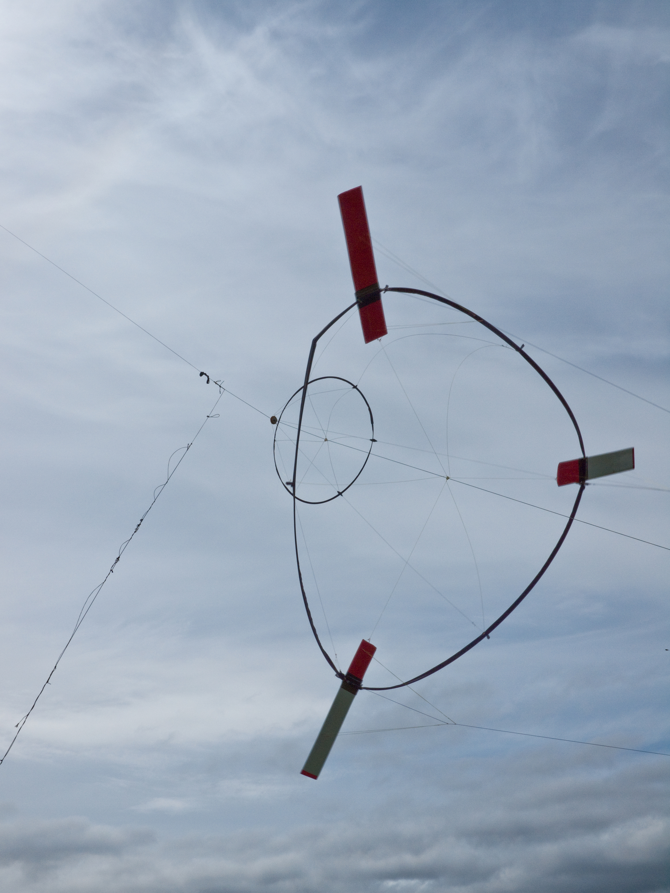
Because the kites expand the ring they don’t need rigidity in the ring. This is kite ring height already.
Looking forward to sharing more, in due course.
No single link. There have been hundreds of posts on scaling limits. Each one has a link.
Of course, the question is not decided by a link or not, but how the scaling laws work. If you have not tangibly observed scaling trends in practice, no link can change that.
Again, I am just asking if you have any idea at what scale rigid members start to be too problematic.
kPower observes complex rigid member scaling problems kick-in >3m length scale. Do you have any number to compare, link-or-not?
A 10m length scale is about tops, and that takes superior wind to pay.
@kitefreak you could not expect @Rodread to scour piles of old forum posts, whith low signal to noise ratio to find documentation about your claim. Such R&D you are mentioning should be linked to quite easily with a few links, or at least you should be able to explain what this R&D contained and led to.
The way your argumentation is here, you are not really adding to the argument, just throwing out unsubstantiated claims… If you could explain your claim in an inderstandable manner, it could shift @Rodread‘s focus, effectively advancing AWE by freeing up his time from wasted effort.
As it stands right now, you have instead wasted mine and @Rodread’s time and thus held back AWE development (if only an infinitessemal amount).
2 Likes
Tallak,
Its called expert heuristic reasoning. Its able to reason over the case-base of known successful kites. The largest known stick kites are marginal monsters not very much larger than 10m length scales.
Nobody expects Rod to scour old Forum posts, that’s my point. The best links are general aviation scaling law texts, but there is no one good look-up link in AWE yet. At best Rod has read many of the Old Forum posts himself over the years. Lets count on SkyMill to better find the effective scaling limit for rigid AWES. They should have some idea of a scaling barrier that meets your requirements, hopefully better than if you tried to read years of past posts.
“As it stands right now” you have no way of proving your own conjecture I have held back AWE with my upscaling studies over the years, including scaling laws posts on this Forum. At least I have tried hard to make the case for severe kite-scaling limits of rigid structure, even if you do not find the case understandable or convincing.
kPower has put up a number (>3m), subject to future third-party verification. Lets see if anyone else has a numeric estimation, and then rely on real-world outcomes to decide whose number was best, however it was derived.
Please do provide any better source of yours for effective scaling limits on various AWE architectures. Having no idea of the limits is a poor option. Criticizing anyone else’s try is rather pointless if you have no ideal citation on offer either, nor any grasp of the answer before a citation comes available.
Here is my main contribution here, to compare to your critique:
"What this simulation may not be capturing is transient extreme peak loads on members caused by many real-world factors.
A better data source may be current breaking statistics of rigid shafts (ST) and tensioned hoops (Daisy), as compared with baseline robustness and crashworthiness of pure soft WECS (ie standard power kites).
kPower R&D suggests ST and Daisy approaches are already near practical scaling limits. Calculation of required reliability, aka safety factor, is part of the determination."
Rather than data-mine-on-demand the old AWES Forum, lets start review with a link to basic scaling law discussion in RC world, as shared on the old forum. Note that wind velocity does not scale in our case, but the RC folks just know they have to fly faster to stay up in a larger model. Let me know if more past links are wanted, all the way to complex aerospace papers on scaling effects. Sorry if you think my efforts in scaling law awareness can never be good enough, at least they have been-
2 Likes
If you look back to a former discussion about the ST windmill, I have provided quite a few arguments about scaling, all grounded in laws of physics. They might not be correct though. Discussing such would be one point of writing on a forum. Statements with no explanation though, right or wrong, do not really add value, because you should not expect readers to accept an argument without explanation.
The link you provided though is quite good, though the relevance to your prior arguments I fail to see…
2 Likes
Yes please, more links to relevant research is always welcome.
Tallak, Lets honor your desire for more explanation. I also want explanation of some of your positions on scaling, like how you account for scaling factors I have invoked, like mass vs area and wing loading, for which I still await your technical response. I’ll continue to provide links as requested.
1 Like
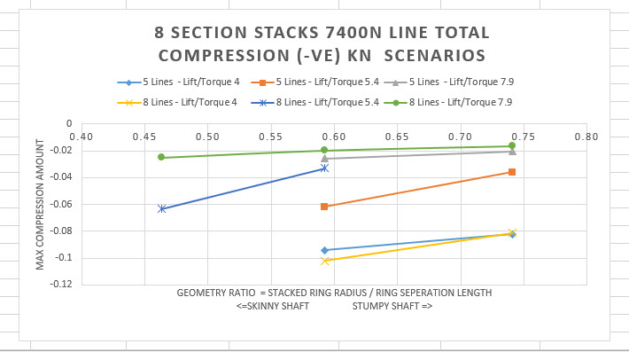
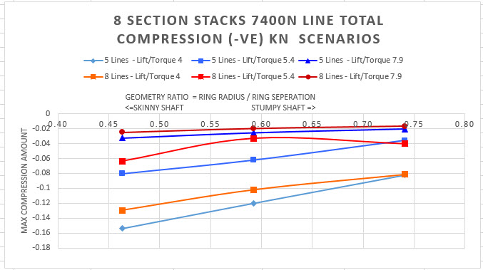
The difference between a skinny shaft and a stumpy shaft looks to be still low.
1 Like
I am a programmer/control engineer guy and can only say general things about mechanical scaling. But I understand the cubic mass scaling law is imprecise, and I see no reason that AWE should scale for some time still. When those limits are reached we will need to consider them, but right now, based on generic scaling laws, it is unclear which limitation will hit us first, and at what scale. Design optimizations seems to be the way to counteract scaling laws
1 Like
I wonder if using full rotors could favor stumpy shafts thanks to a higher torque transfer potential, allowing Daisy to scale more in diameter. Indeed the current rotors with a large hollow seem to more undergo the compression effect then buckling.
1 Like
Tallak. In fact, we have identified a large number of scaling factors, not just Galileo’s fundamental square-cube scaling. There are complex economic, operational, and regulatory scaling factors.
For example, FAA/ICAO regulatory factors use specific mass and velocity classes, relating to inherent scaling physics and safety statistics at the same time.
OK a consistent approach is starting to pay off … Maybe I should be a bit neater in my experimentation like a scientist… nah. Still a couple old odd results to test… Each point takes a few hours though. Weirdly enough the last force finding routine converged in ridiculously few cycles as it’s report shows below.
5 7400 32 4.010781 54 0.592593 422.618726 37.618256 " Number of lines 5.0
line tension N 7400.0
Lift to Torque ratio 4.010781
line Length L 54.0
ring radius 32.0
r/L Geometry Ratio 0.592593
stack length after form find 422.618726
stack length before form find 432.0
stack length ratio 1.022198
Torque vector each line input N 358.044405
edge lengths around hoop 37.618256
line strength 10000000.0" 10285000 “Anchor Forces (kN),1.458981,1.453812,1.481005,1.50736,1.491023,Max Axial Cable Force(kN),1.512898,Average Axial Cable Force (kN),1.481713,Cable Area mm2,1.327323,E - Modulus MPa,10000000.0,Max Pretension,10000,Max Line Stress MPa,1139.811,Average Line Stress MPa,1116.316775,Rung bar Modulus,230000.0,Rung Bar area mm2,19.634954,Max Rung Bar Axial Force(kN)-=compression,-0.119941,Max Rung Stress MPa,-6.109,Max Utility,0.002095,Kite Load Forces N,1469.748598,1471.757365,1485.118866,1491.366491,1481.896673,Itterations for force finding,180,
input load position, {363.447758, -30.167177, 216.612662}, {380.56673, -19.469376, 184.871813}, {380.875384, 18.133471, 183.93655}, {363.947337, 30.675676, 215.097994}, {353.178098, 0.824465, 235.294409}
total input nodal load in kN, {1.400866,-0.120138,0.428138}, {1.342705,0.283653,0.531747}, {1.142419,0.295442,0.90176}, {1.076824,-0.101054,1.026846}, {1.236526,-0.3579,0.734117}
component input nodal load in torque direction kN, 0.316591, 0.325704, 0.381619, 0.405245, 0.369002
Torque input kNm ,
load position, {0.000116, 31.999964, 0.000087}, {-15.354602, 9.888519, 26.276439}, {-9.4896, -25.888531, 16.239736}, {9.489843, -25.888503, -16.239661}, {15.354765, 9.888553, -26.276353}
nodal load in kN, {-1.124413,0.042633,-0.928711}, {-1.231015,0.270006,-0.724754}, {-1.39444,0.124345,-0.483169}, {-1.392664,-0.202505,-0.540012}, {-1.222134,-0.24869,-0.817124}
load component in torque direction kN, 0.234229, 0.257589, 0.304107, 0.31002, 0.263918
Torque output kNm ,
Weight of rungs in kg”
1 Like
Do you have a figure to go with those?
Do I ever,… I’m told I look amazing
But I’m not sure that’s what you’re asking here…
Ollie has done a much more efficient and clean first principles modelling job (not that kind of modelling…) Network Kites and Daisy network kite rotors
More info in these 2 tweets
