"Flight Stability of Rigid Wing Airborne Wind Energy Systems"

Authors: Filippo Trevisi, Alessandro Croce, Carlo E.D. Riboldi

PDF available

Abstract

The flight mechanics of rigid wing Airborne Wind Energy Systems (AWESs) is fundamentally different from the one of conventional aircrafts. The presence of the tether largely impacts the system dynamics, making the flying craft to experience forces which can be an order of magnitude larger than those experienced by conventional aircrafts. Moreover, an AWES needs to deal with a sustained yet unpredictable wind, and the ensuing requirements for flight maneuvers in order to achieve prescribed control and power production goals. A way to maximize energy capture while facing disturbances without requiring an excessive contribution from active control is that of suitably designing the AWES craft to feature good flight dynamics characteristics. In this study, a baseline circular flight path is considered, and a steady state condition is defined by modeling all fluctuating dynamic terms over the flight loop as disturbances. In-flight stability is studied by linearizing the equations of motion on this baseline trajectory. In populating a linearized dynamic model, analytical derivatives of external forces are computed by applying well-known aerodynamic theories, allowing for a fast formulation of the linearized problem and for a quantitative understanding of how design parameters influence stability. A complete eigenanalysis of an example tethered system is carried out, showing that a stable-by-design AWES can be obtained and how. With the help of the example, it is shown how conventional aircraft eigenmodes are modified for an AWES and new eigenmodes, typical of AWESs, are introduced and explained. The modeling approach presented in the paper sets the basis for a holistic design of AWES that will follow this work.
https://twitter.com/myjournals/status/1460993476221407241

2 Likes

I’m sure all those beautifully complex calculations were great fun to do.
That article is a classic fail for me - from the very start - YET AGAIN
@rschmehl how can you approve something which says

  1. AWESs flying crosswind can generate power in two ways

  2. Ground-Gen AWESs produce power cyclically

  3. No real steady-state can be achieved during power generation because of the continuous maneuvers of AWESs 
 The fictitious steady-state motion

That is a disgrace

1 Like

@Rodread thanks for pointing this out. But please calm down. This was not intentional. As editors we can not scrutinize every sentence of a paper but we have to rely on the peer reviewers. And apparently this was overlooked. We are now trying our best to correct what we think needs to be corrected. I will get back to you.

1 Like

Hi @rschmehl , the question of the “two ways” by @Rodread is current because it concerns a large part of scientific publications, starting from the moment when almost all the companies went to groundgen (yo-yo) or flygen modes.

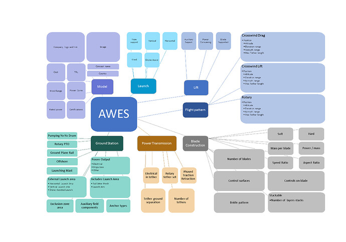
Perhaps one way to fix this would be to affix your AWES classification, which fits into one page.

1 Like

Hi @PierreB the paper in question now refers to the AWES classification scheme (Fig. 2) in the review paper that I co-authored with many other researchers: Electricity in the air.pdf (7.2 MB). I will provide a more detailed response to the remarks of @Rodread in short.

2 Likes

But there are essentially two ways? Lift and Drag mode? Or a combination of those


Wrt to ground gen being cyclic I guess that is essentially thue, but very misleading if that refers to having a production and return phase

The third point is obviously false.

I must support @Rodread on this that repeating these trueisms is hurting the undergrowth of AWE design by giving the impression that every design suffers the limitations of a single specific design

1 Like

Thanks for the clarifications.
Fair enough, it’s all basically lift or drag, but there is a continuum of means by which energy can be extracted form a kite between lift and drag. It’s not only 2 methods.
I may be making a minor point
Kites can push. You can knock a wellie over with a kite.
Pushing a turbine through the air - yeah that’s drag mode.

Further clarification
It doesn’t have to all be 1 tether which restrains the continuum between lift and drag.
Tehers can also be fore and aft or out from the tips.

A rotor flight path - is often exactly the same as a “crosswind” flight path.

A single rigid wing kite on a single line is not the only means to deploy rigid wing AWES.

A kite turbine has steady-state mechanical drag mode operation which relies on strong lift too

All the best until next time I have this rant

A post was merged into an existing topic: Slow Chat

It looks like an interesting and relevant paper.

You seem to be focusing on a minor point and ignoring the interesting bits.

The study seems relevant for your design too.

Personally, after 13 years of this incessant drivel, I don’t think any more “papers” are worth reading, and I challenge any supposed “player” out there to come with any compelling AWE system useful for any purpose. I’ve been saying nobody knows what they are doing the whole time, to great resistance, but where are we now? After well over a decade of constant hype, where is a single system in use today? What good is another “paper”?

1 Like

True, I read through the stability paper
and in terms of stabilising a classic glider , tethered as an AWES it’s very good and able to adapt bridle geometry etc to the ideal. It’s interesting and could be relevant to many designs.
It is however pre-determined in it’s outlook
The research is biased in terms of where it is steered.
It assumes the incumbent designs don’t need to be tested for best fit validity.
I will call it out
and I intend to test this validity severly

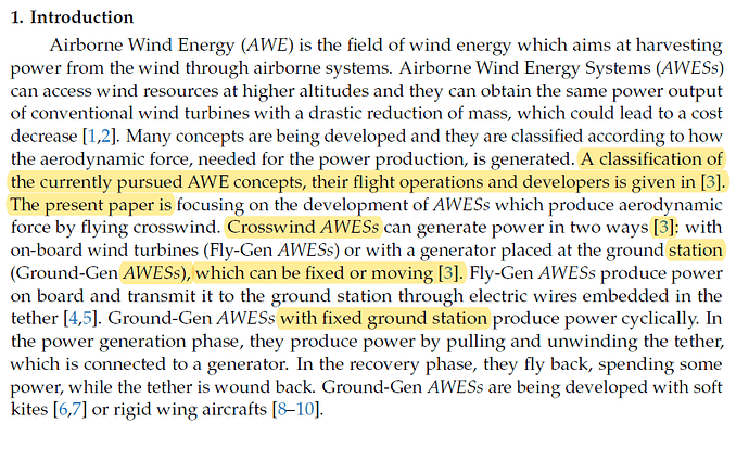
@Rodread: the introduction and literature references were changed by the authors as follows:


This should now be correct, in line with the classification diagram in reference [3]. The main point is that the scope of the paper is restricted to crosswind systems only. Rotary kite systems are not considered crosswind systems. As for a regular HAWT, the individual blades operate crosswind, the rotor as a whole does not.

Thanks for your feedback!

2 Likes

I ask that we please use text to quote rather than images, as images are impossible for me to read here.

So for me the definition of crosswind that is presented here seems odd. My next question would be whether something like Kiteswarm’s concept then is crosswind or rotary.

Maybe these rigid classifications will break down once multi-kite is more mainstream. With the definitions provided here most rotary rigs with bridles are not crosswind though their individual kites are.

There is also the perfectly sound example of a «Daisy» style rig with only one kite and torsional transfer - if having one tether can still constitute to torsion?

These classifications dont interest me a lot. Only the physics involved in each specific concept does.

Though the classification seems to have glitches, I think the problem here is that most papers have an introductory blurb describing AWE as having only two reasonable design options (as we may illustrate by Kitemill or Windlift), while actually these specific designs have only been verified through popularity.

This is a real problem in academia, and a problem that you @rschmehl seem well positioned to fix simply by asking paper authors to remove these passages and leave the good stuff remaining.

1 Like

Hi @tallakt, thank you for your feedback! You can download the full paper (open access) from the link in the original post. The PDF was updated by the publisher and should reflect the changes that were made by the authors. In my opinion, classification helps to distinguish concepts, and, yes, there are many ways this can be done. I consider the scheme not rigid but expandable and maybe we need different schemes for different purposes? In the end, I agree, it is the physics that count.

About the definition of crosswind operation, the criterion is what we consider to be the kite. For the rotary kites of @Rodread and @someAWE_cb I would say that the kite is the assembly of rigid or inflatable blades that form a rotor. As means of assembly, I would consider more or less rigid elements (that can support compressive forces), other than tether or bridle lines (that can support only tensile forces). In this sense, each rotor would be a kite, of which current implementations can use several ones stacked along the drivetrain. Using this definition, the rotors are not operated in crosswind motion, but in a stationary rotation. For the multi-kite systems like that of Kiteswarms, on the other hand, the individual flying devices are connected by tethers. I think it makes sense to consider these devices as individual kites, also, because they can perform any kind of motion, within the constraints of the tethering. As a consequence of that definition, these kites do perform crosswind maneuvers.

And about the “introductory blurb describing AWE”: such introduction is a required and in my opinion also a very useful element in scientific publications. I will try to use every opportunity to make sure that these introductions are more inclusive, within the scope of the publication.

1 Like

Hi @rschmehl , thank you for the change about AWE classification in the introduction of the discussed paper. The last explains make sense until some point.

But on https://www.researchgate.net/publication/324135034_Airborne_Wind_Energy_Conversion_Using_a_Rotating_Reel_System , page 540, 22.1 Introduction:

The present study proposes a new airborne wind energy system, the RotatingReel Parotor (RRP), which combines a rotary ring kite with a ground-based rotating reel conversion system [8].

On the now defunct rotating reel system the flying and ground rotors are connected only by tethers, with an option of additional lines. So there is, in flight, no “more or less rigid elements (that can support compressive forces), other than tether or bridle lines (that can support only tensile forces).”
So was RRP a rotary or a crosswind kite?

More generally, the line between purely rotary and crosswind kites seems rather blurry.

The current paper seems to aim some different means (airplane structure connected to computerized control) in order to improve flight stability.

In rotary kites flight stability is partially assured by structurally constrained means. Conversely, rotating kites like Daisy aim to move the blades away from each other in order to increase the swept area for minimal additional mass. The flight diameter (about 4 times blade-span) tends to approach the flight diameter of a crosswind kite performing circular figures like Makani wing, which even tends to decrease if we believe the latest projections (about 6 times wing-span, table 2 page 26, NREL Airborne Wind Energy, and even less on preprint, page 19 (" For the targeted wingspan of 60m"), page 23 (“The drag-mode AWE system operates at a constant tether length l ≈ 650 m and follows an near-circular flight path of diameter D ≈ 200 m at a mean elevation of about 17 degrees”) ).

The concerns of rotary and crosswind AWES seem to meet: more sweeping with less material, stability.

The decision remains in the percentage of the material construction and that of the control algorithms.

Therefore, a joint and comparative study of rotary and crosswind AWES, with MEASURED TESTS, might be desirable.

1 Like

Hi @PierreB, thank you for your comments.

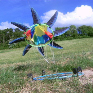
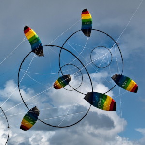
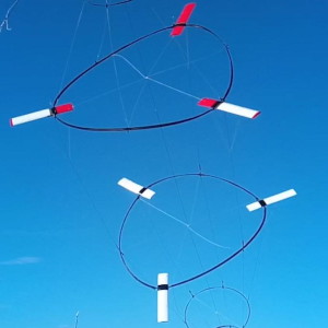
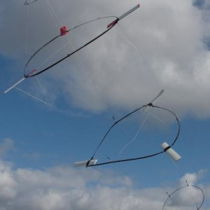
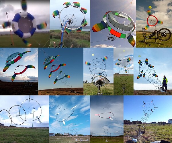
What I meant by “assembly” was the way the wings (rigid or soft) of the airborne part of the system are connected. If there are connected by more or less rigid elements, they form, in my understanding a rotor. Here are some well-know examples or rotary kites used for wind energy harvesting:

rotor1rotor2rotor3rotor4

All these assemblies are rotating at a more or less stationary position (more or less because of disturbances, induced either by the external wind field or by the design itself), transferring the generated torque to the ground, by means of a tensile system that in many cases include also rigid elements. So, I distinguish between the rotors and the drivetrain. I think that it is pretty obvious that the rotors themselves are not performing crosswind motion and in my understanding, the rotating reel parotor (RRP) is a rotary kite system.

Take a horizontal-axis wind turbine. While the rotor blades are operated in crosswind motion, the rotor itself is static, performing at best a (slow) yaw rotation to follow wind direction changes. For that reason I would not call a conventional wind turbine a crosswind machine.

It would make sense, I think, to denote the rotary kite systems as airborne wind turbines (AWT). Makani had introduced the term for their concept, and in fact, their systems were AWTs operated in crosswind motion (with onboard electricity generation and transmission to the ground). While all the concepts depicted above are AWTs operated at a steady position (with tensile rotary power transfer to the ground).

Based on the discussion above, the line between purely rotary and crosswind kites does not seem blurry to me. What do you find blurry?

I do think that a comparative study makes a lot of sense.

1 Like

Thanks for the precisions @rschmehl.

There is no rigid elements on the rotary kite system on the photo below or on some versions of RotoKite.

And also a crosswind kite flying in a circular path (e.g. Makani wing) can be seen as a blade of a rotary system where the center of the flight path is the (also more or less because of disturbances) stationary axis, said blade-wing being the “best and lighter tip part” of the blade of a wind turbine, as often represented.

Hello @PierreB, from your example I can see that you don’t need a “more or less rigid” structure to form a rotary kite. Your example uses a purely tensile structure to achieve that. But the result is in fact a rotor. A rotor, because the mechanical constraints (implemented here by the central parachute-like structure that acts as a hub) force the blades on a rotary motion.

The example of the kite flying a circular path, like the Makani kites, is different, in my opinion. Here there is no mechanical linkage (I should have probably use this term instead of “more or less rigid elements”) of the kite to the center of the circular path. The circular path is generated by active control (one can also imagine a passive control).

I think the question is (that is how I started the post;-) what you consider as kite: is it the individual blade or the rotor. The wind turbine analogy is maybe helpful: blade = kite, rotor = rotary kite. But, as I wrote earlier and what also @tallakt mentioned, these classifications are only helper constructs to somehow distinguish the different concepts. You can develop different classification systems depending on what classification criteria you apply.

1 Like

Oh
This argument is still going on
We need a better classification system.

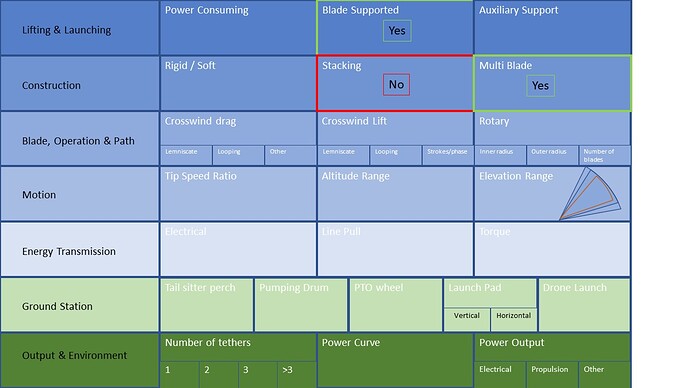
We could collate and share details in a structured format like

a page for each system highlighting where it fits in

or

I don’t think any actively pursued AWES is performing crosswind motion.
A kitesurfer in a bay goes across the wind and back (If they’re boring)

Daisy Kite Turbine Rotors passively fly in an elevated cone and have a lifter.
Drag mode AWES (which push) actively approximately fly a wider end cone, higher up on a longer single line (usually wish they could fly tighter loops)
Lift mode AWES (which pull a tether) actively approximately fly a wider end cone, higher up on a longer line (usually wish they could fly tighter loops) plus an extra squiggle retraction phase.

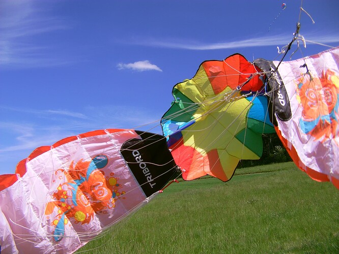
Nothing rigid in pic 1 - barely anything in 3,4,5,6 very little in 7,8,9


Models in pics 7,8,9,11,12 all rotate at the ground station to follow wind changes

Where a kite is bound to a rotor
Surely it is more “crosswind” than a kite able to deviate from that “crosswind” elevated rotary plane

1 Like

Hi @PierreB and @Rodread, it was suggested to fork this blog post into a new one, about classification, also working towards WP5 of the IEA Task 48 where classification is one of the goals.

1 Like