Rotating Reel System

The full text is now available on https://www.researchgate.net/publication/324135034_Airborne_Wind_Energy_Conversion_Using_a_Rotating_Reel_System.

It is a rotary system between a carousel and @Rodread’s Daisy.

To remember the ground ring is horizontal and its diameter should be roughly the same as the flying rotor diameter and the peripheral tethers lengths.

Disadvantage: a large ground ring.

Advantages: a better possibility to optimize the land/space use; take-off by using the ground ring rotation, the generator as motor.

Variants have been studied since, of which a divided flying rotor.

4 Likes

My patent is on https://worldwide.espacenet.com/publicationDetails/originalDocument?FT=D&date=20170317&DB=&locale=fr_EP&CC=FR&NR=3034473B1&KC=B1&ND=4# and also is discussed on Scaling a pilot kite.

Hi. I found time to read the paper, and would like to present some thoughts.

First I’d like to thank you for producing an intetesting paper based on an interesting idea.

1: Use of tether

In general tether is a limited resource for AWE. Using rotational AWE, tether force is spread among multiple tethers, necessary to spread the force evenly along the rotating ring. You have 8 or 16 kites, resulting in 8, 16 or 32 tethers between the ring and the ground ring.

Spreading tether force like this adds tether drag much like opposite of the positive scaling law for tether drag (ie for quadruple force only double tether diameter and drag necessary).

In addition, when using torque, the tether is mostly just statically keeping tension and only the twist component (coming from delta in your paper) is actually generating force in direct mode. For secondary mode this situation might be a lot better though.

For direct mode half of the tethers are producing while the other half are idle (moving downwind or upwind respectively), I guess as for any carousel like system.

All in all the «wasteful» use of tether compared to Flygen/yoyo wil probably result in lower altitudes attained and more pressure to scale huge in order to access higher altitude winds.

Having short tethers should lead to increased elevation angles and thus higher cosine losses.

Building a wind power plant for shorter tether lengths may well be worthwhile though.

2: Rotational speed when scaling

For the relatively small prototype you get a speed of 1 Hz. Once the kite ring scales, the crosswind speed should be constant if lift-to-drag remains constant. Thus the rotational speed should decrease with scale.

This is a problem because transfer of energy is proportional with rotational speed. The torque is limited by geometry and kite pull, suggesting that a gearbox could be useful though probably infeasible.

3: Secondary mode

I dont fully understand this, but it seems to me that the travelled distance is quite short while the amount if tension difference between two opposite tethers has some practical limitations, thereby limiting the amount of energy that may be extracted. Perhaps with scale secondary mode could become more useful?

4: Depower

As the generator must soak up generated energy without getting delta ~ 180 degrees, there seems to be a requirement to depower the wings on the kite side. I think this cannot be avoided in practice. this means more control either through additional tethers or electric actuators on the wings. Passive solutions might also exist for this.

(still reading…)

Please accept these comments as constructive feedback and not an attempt to kill the idea. At least for me, there seems still seems like there might be a working concept in here…
1 Like

I could agree with some of your comments. After a deeper analysis the secondary mode is seen only as an adjustement of the tethers during the rotation, not to do the main generation.

However the FIG 22.18 shows the transferable torque according to the distance between the ground rotor and the flying rotor. The transferable torque can be high but only if the two rotors are close to each other, implying a huge ground (and also flying) rotor in order to reach a significant altitude. Similar observations could be made for any carousel.

So it appears that Flygen/yoyo systems are probably more suitable. I conceived Rotating Reel to maximize the space but such a maximization could also be achieved by using flygen or yoyo methods.

1 Like

The linear speed is taking into account, not the rpm. It is the same for other carousels.

The tethers upwind are in full length, while the tethers downwind are in low length, limiting drag.

The biggest problem we see is the limited height for a significant transferable torque. The limited height applies also to other carousels as (like for rotating reel) the altitude reachable by the kites is proportional to the diameter of the ground ring.

Indeed the Fig. 22.4 represents a phase lag.

The complete depower is achieved with the central rope that pulls the summit of the Parotor, the peripheral tethers being slacked. I used something like this system with Solar balloon jumping using an external central rope to deflate the balloon by turning it over.

Will this constitute to prior art?

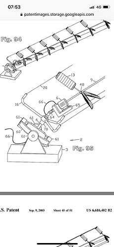
Patent 6616402 by @dougselsam

The patent with the search report is available on https://worldwide.espacenet.com/publicationDetails/originalDocument?FT=D&date=20170317&DB=&locale=fr_EP&CC=FR&NR=3034473B1&KC=B1&ND=4# and on
the attachments (complete patent and search report alone).
FR3034473B1.pdf (964.5 KB)
french-search-report1500663.PDF (460.1 KB)

It is a good search report with only three A, so no relevant prior art, and the patent 6616402 is not even among the three A.

1 Like

You don’t need a massive ground ring to transmit torque over tensile lines.
Tethered rotors (Or just rings) can be stacked (as in the case of Daisy tensile torque tube) and reliably transmit torque. They can reliably fail too. Works when the torque compression is kept below the capability of the ring. Also when the spacing between rings is a good bit less than the ring diameter there is no risk of over twisting the tethers.
This stacked rotors and rings method relies on keeping the “ground ring” axis aligned with the stack axis… It’s more of a tilted carousel. This is harder to make on huge scales but it doesn’t need to be when we are dealing with stacked torque accumulation.

1 Like

Indeed it can be an interesting possibility. Perhaps the rotating reel system could be applied for Daisy, putting the ground ring generator at the horizontal, that with little transmission losses as the first rotating kite is close to the ground ring.

If the stacked Daisy is something like 800 m height and 100 m diameter, the rotating reel system could be useful, allowing the ground generator to be at the horizontal.

This applies to single layer ground to rotor systems.
Stack your rotating reel and this changes.
As for using the ground plane for the power take off with a vertical axis.
Why go to that bother? There will be a lot of extra wear on active lines.
There’s quite an array of tilted carousel type rides at a fairground List of amusement rides - Wikipedia
You just need a whopping good big thrust bearing capacity to handle the axial tension… And good anchoring behind (upwind of the ground rotor)

True. My patent mentions also several layers in the figure 2.
FR3034473B1.pdf (964.5 KB)

Also another advantage of the rotating reel system is the transmission with ropes, with no rigid parts apart the kites.
I think that stacked rotors can aslo work as torque ladder or torque rings.

This cannot scale as well as the rotating reel rope transmission.
Indeed the link shows a big mast with a gear to work the wheel. This cannot be applied for large scales. The rotating reel system uses far less material.

Congratulations on inventing multiple layer stacked rotor kite power

Not so much with some improvements. The wear would be similar to the wear by using the pumping mode or even less as the motion is more regular. And a flat ground generator compensates it. A tilted generator cannot scale well and also doesn’t allow an efficient take-off-landing arrangement.

Thanks. It is not “inventing” as such, but a possibility for this system.

1 Like

Tilted generators can easily launch and recover rotors up and down an established lift line.
I’ve only ever launched from fully extended as I’m zero budget

In a complete automated system a tilted generator should be settled on a ground ring with a motor and ball bearing in order to face the wind direction.
With a rotating reel system the ground ring is also the generator, saving material as a flat horizontal ring is able to face any wind directions. For small devices it is a small advantage at the best. But for larger devices it can be useful.

1 Like

To balance the running lines the horizontal ring needs active winching on each line
or possibly
looser downwind lines and a sag or elastic in the shaft with strong lower flying rings… not very strong stack tension sounding

back to the active winching… that’s a lot of tension, a lot of control, a lot of power, a lot of machinery, on a lot of lines for a problem which can be solved with a thrust bearing…

However… Please dispute what I say because this needs - no demands- investment in more qualified detailed scientific argument. It’s time for the politicians and wealth funds to put their money where our kids future is . I’m for 1 am sick and fed-up of waiting for their input.

Better analysis than I can give you on the difference between Daisy and Rotating reel…

1 Like