This is very exciting for me, though I’m not sure if the verdict is good or bad for the Pyramid this time. I am attaching the poster image from LinkedIn for those that don’t have access or dont care to use LinkedIn. Hope we can get the full paper later.
More love for the «hovering» class of AWE then, right @Rodread ? [using my terms at every possible occasion]
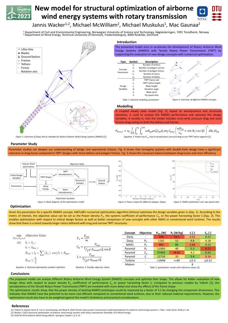
Link to full paper Structural optimisation of airborne wind energy systems with rotary transmission - DTU Findit
Its a good paper, in particular for master level.
It’s really well written. Very clear.
I think there’s a couple of odd results but in such a complex model with so many relevant factors any decision could throw a spanner in the works.
Can’t wait to gather round, get drunk with you and Christof and argue in a comedy fashion over who’s TRPT is best ![]()
![]()
![]()
![]()
![]()
![]()
![]()
One cannot help but think of @dougselsam’s SuperTurbine ™ regarding torque transfer rotary systems, and more particularly embodiment including a TRPT such as represented at least on some figures reproduced below, among other figures (such like Fig. 88) from:

FIG. 84 shows a downwind perspective side view of the sixty-third embodiment, having multiple horizontal axis type rotors connected by helical torque transmitting lashing, a buoyant lifting body, and a directionally compliant base.

FIG. 85 is a side perspective view of the sixty-fourth embodiment, having buoyant horizontal axis type rotors, held by torque transmitting lashing, with no central shaft.
“…torque transmitting lashing, with no central shaft.” Other terms to disclose TRPT.
What matters is not the invention of the term TRPT, but the invention of the TRPT itself, and this is rightly considered by patent examiners who are more attached (dare I say it) to the structural and functional characteristics than to the term subsequently assigned.
I would have liked to have found these elements in the publication under consideration.
@dougselsam looks to be the inventor of TRPT (not the term as such, but the structure), in a similar way he is the inventor of Laddermill (not the term as such, but the device):
Agreed, Doug was the first to apply “TRPT” in kite power .
To be clear - The key difference with Doug’s designs and My Kite Turbines is using blades for rotor expansion and avoiding rigid hub and shaft components allows larger blade sweep area for high speed flight high torque not high rpm
Not to mention Rudy Harburg’s patent:

Yep, Rudy was first to design and patent… did he ever make one?
I dont care about who invented what and who patented what to be honest. Oh it could be an interesting trivia or have some monetary or organizational consequences, so its not totallt unimportant.
BUT
Just because @dougselsam came up with TRPT designs a while back does not mean that these designs should automatically be included in every paper.
As the «inventor/designer» of the Pyramid I would argue that it is a more interesting design than the Superturbines pictured in the patent. And I have provided lots of concrete work to point to a real solution. I also made a simulator. I think some of these reasons could be why The Pyramid was selected rather than a Selsam design. Or the fact that we (me, @Rodread and @someAWE_cb) went to AWEC and shared our designs with the supervisor behind this paper.
That should also be something to think about for those constantly whining that conferences are useless. This is what organic growth looks like. Conferences do work.
Also, wrt The Pyramid; I made it but my starting point was; could we do TRPT with a kite like the one we use in Kitemill, and also solve launch and land in a way similar to what Enerkite does? I would be a fool to think «The Pyramid» was my invention. I was just rehashing things that I had previously seen. It doesnt matter really who came up with which part of the design. What matters is that it could be a step closer to something actually producing power…
This is an interesting feature to allow some scaling potential. The devices represented in the figures 85 and 88 and some other figures are concerned. Sometimes older designs include some solutions that can be benefit for the newer.
Precision: the document under discussion mentions in the limitations 7.1, page 46, the question the catenary shape with regard to the weight and length of TRPT as I have done.
Yes,
it says
The TRPT frames are assumed to rotate in parallel planes with a common axis of rotation.
In practice, the weight of its components causes the TRPT network to form a catenary
shape. This can creates cyclic slack in the rotating tethers, increase fatigue and will effect
the final elevation angle of the rotor. The effect is stronger for long TRPT networks and
can be minimised through lightweight materials and high axial tension.
In the structural analysis of the tether and frame components, centrifugal forces not in
cluded. Instead the focus is on preventing buckling of frames due to high deformations.
Further, the tether and frame mass had relatively little impact on the total system mass.
This means that in practice the designs might rather be based on available material sizes.
Much against the advice from this paper -
It could be argued that the rotor and TRPT should be optimised separately. The difficulty of that approach is the influence they have on one another. If for example the rotor design is kept constant and only the TRPT frame radii and tether lengths are optimised, the resulting TRPT drag would affect the optimal tip speed ratio (as seen in figure 5.4). Figure 5.5 showed that the optimal blade pitch depends on the tip speed ratio and would therefore also have to change. Due to this circular dependency, it was decided to optimise rotor and TRPT design variables together at the cost of computation time.
I am currently trying to develop a new TRPT optimiser using a genetic algorithm …
One thing the paper highlighted which surprised everyone was the
It seems like the solver increases the frame radii to reach higher altitudes. However it is
unclear why the frame below the rotor is so slim. One theory is, that the weight contribution
of the rotor, lifter and ground station are so much large, that the additional frame mass
due to high forces is not very important.

Before plugging my model in, playing with the sliders in my basic interactive sim maybe hints towards why the optimizer chose a small ring 2nd from the top. … Because the top ring is so large It really minimises line twist in the first stage… so second ring structural deformation is going to be minimal it really depends on which objectives we prioritise in the solution sets. Given the huge parameter numbers, there will be many local minima. Choosing an optimiser result depends on what mix of objectives you’re optimizing for and selecting that mix from within the set of solutions …
My 1/2 plan is to run monstrously big evolved population sets and explore / compare trends
wish me luck
That [the picture] looks not right… with too many parameters optimization should maybe start from a manual design approach set of parameters
This mess was the grasshopper definition I used to try manually analyse the TRPT design space last time

This time I’m trying to add in the complexity of an automated genetic solver on top of this form and force finding system but with added buckling analysis for fun
A lot of dead ends found in incompatible buckling & displacement modelling software
Not a great re-start so far